


 Competitive Coexistence: Post-War Strategic Outlook")

 Extract (6-MSITC) in Healthy Older Adults")
: An In-Depth Exploration into its Thermogenic Role and Social Significance")


The evolution of defense technologies and information technology is bringing to the extreme the opposite socio-political fronts.
The international powers have begun to clash both on the military strategic plan and on the economic one.
The technological evolution and its offer on the international market functions as a flywheel of discord, because buyers are often involved in strategic purchases for defense, from nations of the opposite faction.
Many nations considered “hostile and terrorist” have made enormous strides in the missile sector – a classic example and North Korea.
It is not the first time that a war “calculated at the table” explodes in hot spots on the planet to force the world order to a new reorganization.
The collateral damages … are collateral … and as such calculated and accepted to reach the ultimate goal.
It does not matter if 1 million people die … the prospect of a future geopolitics … prevails over the value of today.
Following and studying the international military strategic political events for over 30 years, I have repeatedly written reports and analyzes.
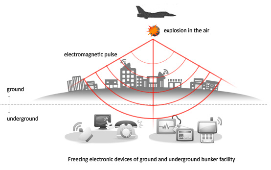
This time I pointed my finger … on what I call “EMP – the spark that will extinguish the world”
Everything will go off …. from medical devices implanted in people … to defense systems.
I’ll try to clarify the ideas and … if you have patience read everything until the end …..
It is important to really understand the problem!
(EMP) Electromagnetic Pulse is an instantaneous, intense energy field that can overload or disrupt at a distance numerous electrical systems and high technology microcircuits, which are especially sensitive to power surges.
An electromagnetic pulse (EMP) is defined by the Technology Division of the National Communications System as a wide frequency range, high-intensity, extremely rapid, and short duration burst of electromagnetic energy which produces electric and magnetic fields which can couple to metallic conductors associated with electrical and electronic systems to produce damaging current and voltage surges.
A noted expert in the field of nuclear weapons and EMP effects, Dr. Lowell Wood, characterized EMP as being similar to “…very intense static electricity that is carried on radio-frequency electromagnetic waves.”
Although EMP may be produced by both nuclear and non-nuclear detonation.
In general, a nuclear EMP is caused by the interaction of high energy nuclear radiation with atoms in the atmosphere.
At altitudes above approximately 40 km, the EMP component becomes particularly significant due to the large volume of the atmosphere underneath the exploding weapon that is available to interact with the high energy nuclear radiation.
According to Dr. Wood, the nuclear weapon’s high energy nuclear radiations interact with the air molecules and essentially transform the atmosphere underneath the explosion into a gigantic radio- transmitter antenna.

FIGURE 1. HEMP GENERATION MECHANISM12
Dr. Gary Smith, as the Director of the Johns Hopkins University Applied Physics Lab, testified that there are two overriding characteristics that make a HEMP attack unique.
These characteristics are of particular interest to those concerned with an effective homeland defense and homeland security.
First, the area affected by the EMP signal can be continental in scope.
As the altitude of the detonation increases, the area in line of sight to the radiation and, therefore subjected to direct EMP effects, also increases.
For a detonation altitude of approximately 500 km, the entire continental United States, and portions of Canada and Mexico would be affected (although at the edges of the area, the field intensity would be about half of the peak levels and the field strength would not be uniform over the entire area).

The second HEMP characteristic of interest is that the peak electromagnetic field amplitude and the speed at which it increases are extremely high.
Although EMP has often been compared to a lightning strike, this is only useful as an illustrative comparison to understand the scale of some of the effects.
There are significant differences.
For example, HEMP has several phases, each generated by different effects of the nuclear weapon.
Each of the phases has unique characteristics and poses different protection challenges.
Also, EMP Also, EMP generated by an exoatmospheric nuclear explosion develops its peak electrical field much faster than lightning, making it harder to protect against.
Finally, lightning is a localized event while the implications of a continental-sized electromagnetic field create unique propagation effects.
Since an electromagnetic field interacts with a metallic conductor to induce currents to flow through them, any metallic object (such as power lines, local area network cables, or even plumbing) can act as an antenna which gathers in the EMP signal and converts it to current flow.
Long-line conductors such as power lines and metallic communication cables can further extend these currents throughout and beyond the area illuminated by the line-of-sight HEMP effects.
The direct and indirect electromagnetic coupling effects are the means by which an EMP signal generated by a high altitude nuclear detonation can cause near-instantaneous, potentially damaging voltages and currents in unprotected electronic circuits and components throughout an entire continental-sized area.
Modern electronics and computer systems are extensively based on semiconductor- based integrated circuit technology, and various other circuits and devices.
Due to the exceptional sensitivity of modern electronics to relatively small amounts of energy, the extreme voltages and/or current spikes produced by an EMP event can upset and even create irreversible damage to unshielded or specially designed electronic and computer devices.
This is why a HEMP attack is so potentially catastrophic for the United States – it is the most electronically dependent nation in the world.
Essentially post- attack America would remain stuck in the 19 th Century until replacement electrical equipment and components were available (most likely having to be brought in from abroad) and installed.
Of course, this assumes that the vast variety of skills required to conduct such a recovery could be located and efficiently employed in a population attempting merely to survive the anarchy that would inevitably result from the long-term disruption of essentially every portion of the nation’s infrastructure.
NUCLEAR WEAPON DELIVERY
To conduct a successful HEMP attack on any nation, the significant challenge is to get the weapon to the desired altitude and location.
Due to the tremendous area affected by a HEMP attack, exact geographic accuracy need not be a primary requirement.
Obviously, an Intercontinental Ballistic Missile (ICBM) with sufficient payload capacity to carry the weapon would suffice.
Similarly, weapons traditionally considered as either short, medium, or intermediate range ballistic missiles (SRBM or MRBM, IRBM) would also be suitable, if of sufficient payload capacity and positioned at a launch point close enough to the United States.
The 1998 Commission to Assess the Ballistic Missile Threat to the United States (the Rumsfeld Commission) observed that using old patterns of ballistic missile development as guides to evaluating current threats are misleading.
Approaches to ballistic missile development and deployment that were not used by the major Cold War powers for reasons of inefficiency, safety, or quality control may be perfectly acceptable to a nation or group seeking the means to threaten the United States.
The transfer of operational missile systems was also cited as a specific concern.
Similarly, the Rumsfeld Commission specifically identified several countries that were pursuing a sea launch capability (a troubling aspect of this development is the increased difficulty of correctly assigning responsibility for such an attack).
This development was recognized as expanding the potential threat envelope to shorter range missiles such as the Scud series.
Within this framework of missile proliferation uncertainty, an overview of nations assessed to possess nuclear capable ballistic missiles is in order.
Of the existing nuclear armed nations that are currently of concern, Russia and China both possess both land and sea based ballistic missile systems capable of conducting a HEMP attack.
North Korea, Iran, and Pakistan possessed a range of nuclear capable ballistic missiles ) with sufficient payload capacity to carry EMP weapon.
The report also cited Syria as having a domestic Scud production program as well as a development program to produce longer range Scud variant. In recent months Russia has decided to install the S-300 missile system in Syria!!!
Possession of nuclear weapon and ballistic missile capability are the entry level requirements to threaten any nations with a HEMP attack.
Sufficient technical expertise must be available to integrate the systems together with a degree of confidence that the system will perform as required.
Countries that possess a domestic ballistic missile manufacturing program undoubtedly possess sufficient technical expertise to do so.
Having briefly discussed the risk posed by the proliferation of both nuclear and ballistic missile technologies, an assessment of the effectiveness of the dual security strategies of the United States will determine if current prevention and preparedness measures to prevent a HEMP attack are adequate.
Background on EMP
An EMP is the burst of electromagnetic radiation created, for instance, when a nuclear weapon is detonated or when a non-nuclear EMP weapon is used.
EMPs can be high frequency, similar to a flash of lightning, or low frequency, similar to an aurora-induced phenomenon.
The consequences of an EMP can range from permanent physical damage to temporary system disruptions, and can result in fires, electric shocks to people and equipment, and critical service outages.
There are two general classes of EMP of concern:
(1) Nuclear sources of EMP, such as High altitude EMP (HEMP), and
(2) Non-Nuclear sources of EMP (NNEP).
HEMP results from a nuclear detonation typically occurring 15 or more miles above the Earth’s surface.
The extent of HEMP effects depends on several factors including the altitude of the detonation, the weapon yield, and whether it was designed for EMP effects.
On the ground, effects may be diminished by the electromagnetic shielding, or “hardening,” of assets.
A high-altitude burst could blanket the entire continental United States and cause widespread impacts to multiple sectors, including to lifeline sectors, such as the energy and communications.
HEMP threat vectors can originate from a missile, such as a sea-launched ballistic missile; a satellite asset; or a relatively low-cost balloon-borne vehicle.
Non-Nuclear EMP (NNEP) can be created by sources, such as Radio Frequency Weapons or Intentional Electromagnetic Interference devices, which are designed to produce sufficient electromagnetic energy to burn out or disrupt electronic components, systems, and networks.
NNEP devices can be either electrically-driven, where they create narrowband or wideband microwaves, or explosively-driven, where an explosive is used to compress a magnetic field to generate the pulse.
The range of an NNEP is short (typically less than 1 kilometer) and Faraday casings with line filters and surge arresters can mitigate much of the EMP effects.
Potential Impacts to Critical Infrastructure from EMP
We do not fully understand how an EMP event would impact electrical infrastructure, and it is the subject of ongoing analysis.
In some of its forms, EMP could cause widespread disruption and serious damage to electronic devices and networks, including those upon which many critical infrastructures rely.
There is uncertainty over the magnitude and duration of an electric power outage that may result from an EMP event due to ambiguity regarding the actual damage to electric power assets from an event.
Any electric power outage resulting from an EMP event would ultimately depend upon several unknown factors and effects to assets that are challenging to accurately model, making it difficult to provide high-specificity information to electric system planners and system operators.
These variables include characteristics such as the EMP device type, the location of the blast, the height of the blast, the yield of the blast, and design and operating parameters of the electric power system subject to the blast.
Secondary effects of EMP may harm people through induced fires, electric shocks, and disruptions of transportation and critical support systems, such as those at hospitals or sites like nuclear power plants and chemical facilities.
In the development of The National Space Weather Strategy, we recognized that the growing interdependencies of critical infrastructure systems have increased potential vulnerabilities to EMPs and GMDs.
Cross sector protection and mitigation efforts to eliminate or reduce EMP and GMD vulnerabilities are essential components of national preparedness. Protection focuses on capabilities and actions to eliminate vulnerabilities to EMP, and mitigation focuses on long-term vulnerability reduction and enhancing resilience to disasters. Together, these preparedness missions frame a national effort to reduce vulnerabilities and manage risks associated with EMPs, GMDs, and other unbounded events.
Description of High-Altitude Electromagnetic Pulse
HEMP is produced when a nuclear weapon is detonated high above the Earth’s surface, creating gamma-radiation that interacts with the atmosphere to create an instantaneous intense electromagnetic energy field that is harmless to people as it radiates outward, but which can overload computer circuitry with effects similar to, but causing damage much more swiftly than a lightning strike.
The effects of HEMP became fully known to the United States in 1962 during a high-altitude nuclear test (code named “Starfish Prime”) over the Pacific Ocean, when radio stations and electronic equipment were disrupted 800 miles away through parts of Hawaii.
The HEMP effect can span thousands of miles, depending on the altitude and the design and power of the nuclear burst (a single device detonated at an appropriate altitude over Kansas reportedly could affect all of the continental United States), and can be picked up by metallic conductors such as wires or power cables, acting as antennas to conduct the energy shockwave into the electronic systems of cars, airplanes, and communications equipment.
Figure 1. Estimated Area Affected by High-Altitude EMP

Source: Heritage Foundation, Jack Spencer, America’s Vulnerability to a Different Nuclear Threat: An Electromagnetic Pulse, Backgrounder #1372, May 26, 2000, [http://www.heritage.org/Research/ MissileDefense/bg1372.cfm].
Description of High-Power Microwave
Microwaves are characterized by electromagnetic energy with wavelengths as small as centimeters or millimeters, and can be used at moderate power levels for communications or for radar.
High Power Microwaves can be produced as a weapon when a powerful chemical detonation is transformed through a special coil device, called a flux compression generator, into a much stronger electromagnetic field.
Other methods, such as combining reactive chemicals or using powerful batteries and capacitors, can also be used to create a reusable HPM weapon.
HPM energy can be focused using a specially-shaped antenna, or emitter, to produce effects similar to HEMP within a confined area, or over a limited distance.
Unlike HEMP, however, HPM radiation uses shorter wave forms at higher-frequencies which make it highly effective against electronic equipment and more difficult to harden against.
A mechanicallysimple, suitcase-sized device, using a chemical explosive and special focusing antenna, might theoretically produce a one-time, instantaneous HPM shockwave that could disrupt many computers within a 1-mile range.
Also, HPM energy at higher power levels (megawatts), and powered for a longer time interval, reportedly could cause physical harm to persons near the source emitter, or possibly in the path of a narrowly focused energy beam.
Disruptive Capabilities
Studies related to the effects of electromagnetic weapons have been published infrequently, or remain classified.
Nevertheless, it is known that a powerful HEMP field as it radiates outward can interfere with radio frequency links and instantly produce damaging voltage and currents in electronic devices thousands of miles from the nuclear explosion.
Effectiveness is increased if the electronic devices are connected to any metal that could also act as an antenna.
Because infrastructure computer systems are interconnected, a widespread HEMP effect could lead to possible long-term disruption of power, fuel distribution, transportation systems, food and water supplies, hospitals, and law enforcement communications, as well as military communications systems which utilize the civilian infrastructure.
A HEMP attack directed against the Unites States continent might involve a one-megaton nuclear warhead, or a smaller one that is specially-designed, using a burst several hundred miles above the mid-western states to affect computers on both coasts.
However, creating a HEMP effect over an area 250 miles in diameter, an example size for a battlefield, might only require a rocket with a modest altitude and payload capability that could loft a relatively small nuclear device.
If a medium or higher range missile with a nuclear payload were launched from the deck of a freighter at sea, the resulting HEMP could reportedly disable computers over a wide area of the coastal United States.
The disruptive effects of both HEMP and HPM reportedly diminish with distance, and electronic equipment that is turned off is less likely to be damaged.
To produce maximum coverage for the HEMP effect, a nuclear device must explode very high in the atmosphere, too far away from the earth’s surface to cause injury or damage directly from heat or blast.
Also, HEMP produced by the nuclear explosion is instantaneous — too brief to start current flowing within a human body — so there is no effect on people.
However, microwave energy weapons (HPM) are smaller- scale, are delivered at a closer range to the intended target, and can sometimes be emitted for a longer duration.
These capabilities can cause a painful burning sensation or other injury to a person directly in the path of the focused power beam, or can be fatal if a person is too close to the microwave emitter.
Both HEMP and HPM can permanently immobilize vehicles with electronic ignition and control systems.
A high altitude nuclear explosion (that creates HEMP) produces three major energy components that arrive in sequence, and which have measurably different effects that can be cumulatively damaging to electronic equipment.
The first energy component is the initial energy shockwave which lasts about one microsecond, and is similar to extremely intense static electricity that can overload circuitry for every electronic device that is within line of sight of the burst.
A secondary energy component then arrives, which has characteristics that are similar to a lightning strike.
By itself, this second energy component might not be an issue for some critical infrastructure equipment, if anti-lightning protective measures are already in place. However, the rise time of the first component is so rapid and intense that it can destroy many protective measures, allowing the second component to further disrupt the electronic equipment.
The third energy component is a longer-lasting magnetic signal, from about one microsecond to one full second in duration.
This geomagnetic signal causes an effect that is damaging primarily to long-lines electronic equipment.
A localized magnetic effect builds up throughout the length of the transmission lines and then quickly collapses, producing a magnetohydrodynamic (MHD) “heave,” or “late-time,” power surge that overloads equipment connected to the power and telecommunications infrastructure.
This late- time effect adds to the initial HEMP effect, and systems connected to long-lines power and communications systems may be further disrupted by the combined effects. Smaller isolated systems do not collect so much of this third energy component, and are usually disrupted only by the first energy component of HEMP.
An HPM weapon has a shorter possible range than HEMP, but it can induce currents large enough to melt circuitry, or it can cause equipment to gradually fail over a period of minutes, days, or even weeks.
In 2001, a U.S. Comanche helicopter, flying in New York while performing a radar test involving HPM weapons, generated a low-level energy pulse that reportedly disrupted for two weeks the global positioning systems (GPS) being used to land commercial aircraft at a nearby airport in Albany, New York.
Older electrical components, such as vacuum tubes, are generally built more massively, and are more tolerant of electromagnetic pulse.
However, as modern electronics shrink in size, circuitry is becoming increasingly vulnerable to electromagnetic interference.
Therefore, countries with infrastructure that relies on older technology may be less vulnerable to the disabling effects of HEMP or HPM than countries that rely on a higher level of technology.
Hardening Against Attack
Electronic equipment may be hardened by surrounding it with protective metallic shielding which routes damaging electromagnetic fields away from highly sensitive electrical components.
This method, known as Faraday cage protection, is traditionally used to protect electronic equipment from a lightning strike.
However, power surges HEMP or HPM weapons could possibly involve peak currents of tens of millions of amps which can pass through a protective Faraday cage.
Additionally, equipment placed within a Faraday cage may also be made vulnerable by any wires running into to the cage which can conduct the electromagnetic shockwave into the equipment.
Depending on the power level involved, points of entry into the shielded cages can sometimes be protected from electromagnetic pulse by using specially- designed surge protectors, special wire termination procedures, screened isolated transformers, spark gaps, or other types of specially-designed electrical filters.
Critical systems may also be protected by increasing the number of backup units, and by keeping these units dispersed and out of range of the electromagnetic pulse source emitter.
Hardening most military systems, and mass-produced commercial equipment including PCs and communications equipment, against HEMP or HPM reportedly would add from 3% to 10% to the total cost, if the hardening is engineered into the original design.
To retro-fit existing military electrical equipment with hardening would add about 10% to the total cost.
The Early-Time (E1) High-Altitude Electromagnetic Pulse (HEMP) and Its Impact
A HEMP event includes three waveforms: E1, E2, and E3 (see Figure 1):
Figure 1: EMP Waveforms
Source: US Department of Energy, “Electromagnetic Pulse Resilience Action Plan,” p.1.
The E1 waveform is a fast (i.e., nanosecond rise time, hundreds of nanoseconds duration), broad- band pulse that disrupts systems in general, including long-line electrical systems, computers, sensors, and electronic-based control systems.
E1 can generate electric field strengths on the order of tens of thousands of volts per meter.
E1 EMP can affect a wide area, but the intensity drops considerably from the area of maximum intensity, which is geomagnetically south of ground zero of a nuclear burst in the Northern Hemisphere.
The E2 waveform is longer and much lower in amplitude than the E1 waveform.
As an intermediate time pulse, E2 manifests itself by enhancing the EMP currents on long lines in the microsecond and millisecond regime.
The waveform is often described as being “like lightning” and while E2 current pulses are comparable to currents induced by nearby lightning strikes, the E2 pulse’s magnitude is larger than lightning at higher frequencies; therefore the E2 and lightning protection standards are not equivalent.
In addition, because E2 follows E1, E2 protections may have failed due to the initial pulse.
Varying significantly from E1 and E2, the E3 waveform is a low-amplitude, long-duration pulse caused by a nuclear detonation at a high altitude which causes a temporary distortion of the Earth’s magnetic field.
E3 pulses are slow, lasting from tens to hundreds of seconds.
E3 induces currents in so-called “long lines”—notably power and communication lines, pipelines, rail lines, and other vital elements of the Nation’s critical infrastructure.
These conductors act as antennas which may enhance magnetic field coupling and increase EMP/GMD effects, including destabilizing and damaging connected equipment such as electrical transformers.
E3 waveform effects are comparable, but not equivalent, to those from geomagnetic disturbances.
A GMD event typically features multiple peaks of pulses with varying amplitudes over hours or days; E3 typically is a singular pulse more intense and prolonged any one of these peaks.
EMP Exposure and Effects
EMP does not directly have any negative health or safety effects on humans and does not directly interfere with radio communications.
Electronics exposed to EMP, particularly semiconductor components, are at risk of upset; they may not function normally until cycled in power—or can be damaged through a surge in voltage or current.
Significant uncertainty exists regarding EMP impacts both on an asset-level and system-level basis for infrastructure systems.
For example, an E1 pulse may place any electronics within range at risk of upset or damage.
However, existing shielding in some electronics, despite not being specifically designed to do so, may protect against EMP.
Only some combination of shielding, grounding, and filtering, combined with verification testing, can ensure that electronics will function through an E1 EMP.
E3 has an effective wavelength larger than the Earth, so it does not couple with electronics and therefore does not directly affect electronics like E1 EMP.
What it does is create a gradient in ground voltage. A very large conductor, such as the power grid that is grounded over distances of hundreds to thousands of kilometers and not properly configured, can experience a geomagnetically induced current (GIC) across the system because of voltage asymmetries.
These asymmetries can, in turn, induce voltage collapse of the power grid from transformer saturation and damage to high-voltage transformer failure from internal heating.
Again, exact effects depend on many variables including local ground conductivity, details of transformer design, and the exact configuration of a power grid.
This report discusses the threat and impacts of the early-time (E1) HEMP.
This is the earliest part of HEMP (high altitude electromagnetic pulse, generated by an exoatmospheric nuclear burst), encompassing the part of the HEMP that runs out to about a microsecond.
It has the highest amplitude in the HEMP waveform, and typically rises to that peak fast, often in a few nanoseconds. It is driven by the burst’s gammas – very high energy photons, which are produced by nuclear reactions within the nuclear burst.
This discussion does not assume that the reader already has any EMP experience, so it starts at a very tutorial level.
It also continues into more advance discussions, and some physics (engineering, etc.) background might be needed to fully appreciate all the details.
Including all details, even simple ones, was done because, especially with the Internet, there is much erroneous EMP information available.
Much of the best E1 HEMP material is not readily available, and much of what is easily available has inaccuracies.
This is especially true for some of the E1 HEMP information on the Internet.
For example, burst “yield” is often considered as the measure of a nuclear device, and correctly so for the blast and shock produced by a surface burst.
For E1 HEMP the burst yield has much less significance. Maximum E1 HEMP levels on the ground do not correlate well with device yield.
E1 HEMP work has often been done within the classified environment. Two important reasons for this security are:
- HEMP generation is intimately connected to significant design details of a nuclear weapon.
- The work might directly, or indirectly, involve the vulnerability levels of military systems, and we do not want our enemies to know the HEMP levels to which our security forces are
E1 HEMP development is reflected in numerous government supported technical reports, and many are classified.
However there is also much material in open literature, which is applied in this report.
The military has taken E1 HEMP very seriously for a long time, including hardening and testing efforts.
On the civilian side, the problems have not really been addressed.
There has been a wide range in the perception of E1 HEMP as a threat.
There are skeptics – those that think E1 HEMP does not exist, or that the models are wrong, or the field levels are not as bad as calculated.
There are also those who believe we cannot do anything about it – if it happens we will just have to deal with it then.
Then there are others that think every electronic device in the country will fail, and we will go back to the Stone Age.
There are many such exaggerated scenarios; for example, it is doubtful that more than a very small fraction of vehicles will suddenly stop working – but how long will they be able to run with gasoline supply disruptions from possible electric power grid problems?
And much of the open discussions of nuclear burst EM effects deal with E1 HEMP, as it has very large peak fields, and has often been what is meant by the term “HEMP”.
However, there are also other parts to HEMP, and E3 HEMP effects could be just as disastrous to the power grid, or even more so in some cases, than E1 HEMP.
Many perceptions of E1 HEMP effects, and the feeling that nothing can be done about E1 HEMP vulnerabilities, are also erroneous.
Besides accounting for the unlikely chance of a HEMP event, efforts to protect against E1 HEMP effects also tend to have other benefits.
There are other intense EM environments, such as lightning, and switching transients in electric substations, for which there is some overlap in protection methods.
There is also a growing concern of “IEMI” (intentional electromagnetic interference), in which criminal or terrorist elements purposely generate high electromagnetic levels to cause upset or damage to the operation of electronics in a building or a substation.
In this section we will briefly introduce many aspects about E1 HEMP.
Some of it will introduce the subjects that are more thoroughly discussed later, while some will not be discussed further.
This material should provide a good basic understanding of E1 HEMP, its effects, and possible protection. There are many subsections, some short and dealing with a very specific issue.
Historical Prospective
It was anticipated that a nuclear burst would generate electromagnetic signals, and possibly cause problems for electronic equipment.
This proved to be true, and a whole range of EM effects from nuclear bursts were discovered and studied over many years.
For E1 HEMP, initial hypotheses were inadequate, and actual signal levels proved to be much higher than anticipated. A
dequate theories for E1 were not developed until after nuclear testing was moved underground.
There has been extensive theoretical and experimental work on E1 HEMP, including from underground nuclear tests.
Besides work for critical military systems, there were also some early efforts for the telephone network – as seen by one of the first E1 HEMP specification waveforms coming from Bell Laboratories.
However, in the competitive commercial environment it is understandable that such E1 HEMP hardening did not go forward.
Studies were also done by ORNL for various aspects of E1 HEMP effects on the electric power system in the 1980’s.
While over the years interest in E1 HEMP tended to lessen in the U.S., recently it has increased worldwide.
The recent efforts of the EMP Commission have shown a renewed sense that E1 HEMP should not be completely ignored by the civil infrastructure.
The only direct experience with E1 HEMP was in 1962, when the U.S. and USSR both experimented with a few high altitude nuclear bursts. For the U.S., the bursts were over the wide expanse of the sparsely populated South Pacific.
The only real infrastructure was in Hawaii, very far away, and generally consisted of electronic tubes, and power grid relays that were bulky (and hardy) electromechanical devices.
There were some upset and damage effects in Hawaii. The Russian experience, which was over land and more pertinent, was over a vast desert region, also with very antiquated infrastructure equipment.
They did have damage associated with long lines (communications and power insulators), and also damage to diesel generators and radar systems. Now, more than half a century later, and after all the technical advances in our modern infrastructure (solid state electronics), it is certainty true to say that E1 HEMP is likely to be a bigger problem than it was in 1962.
E1 HEMP Effects on Systems
E1 HEMP peak field levels can be very high, and certainly there could be some devices within a system that have some vulnerability to such high levels.
However, typically vulnerabilities involve the intermediate step of having voltages and currents generated on a conductor, and then that signal getting to the fragile device.
The conductor might be deep within the system, such as wiring in the internal circuits, however a major concern is external cabling attached to the system, for two reasons.
First, outside wiring can be very long, which tends to increase coupled signal levels, while internal wires are limited by the enclosure size.
Secondly, the system enclosure and support structure, especially if metallic, attenuates electromagnetic fields and leads to lower coupling for internal wires.
With a peak field of 50 kV/m, even a short “antenna” 10 cm (4 inches) long can mean a voltage of about 5000 volts, and it could be much higher for longer lines.
Power lines, of course, can be very long.
Other possible long lines include communication lines within a facility, such as network lines and phone lines.
For power substations there are also the various sensing and activation lines used for the relaying process that maintains power reliability and tries to lessen harm to the power system from faults.
With the advance of modern systems, and miniaturization of components, the normal operating voltages of systems tends to be a few volts, and so HEMP levels of thousands of volts or more cannot be good for the system.
Also, the operating frequencies of systems, such as computers and various types of controllers, are such that an E1 HEMP pulse would cover many clock cycles. Thus the fact that E1 HEMP type pulses can have effects, as has been found in vulnerability tests, is not surprising.
Typically system effects are separated into two types (although finer gradation is possible):
Temporary Upset Permanent Damage
Damage is fairly clear – something physically happens to some part of the system, such that the system no longer works.
Sometimes the damage might be readily seen, such as a device “blown up”, but other times there may not be any visual damage, yet the system will not work.
It might be that the damage is to a small, but critical, area inside an integrated circuit (IC).
With devices being microscopic, it is believable that even very small energies could be worrisome.
This is why ESD (electrostatic discharge) is such a concern when handing modern electronics.
Besides outright damage to a device, we can also have degradation, in which the device still operates, but its performance is not as good as before the assault by the high level pulse.
Damage can also be ranked by how long it would take to repair, or how easily it could be fixed. In many cases it would involve determining that there is a problem, and what subsystem is broken, and replacing the subsystem.
It might not always be obvious that there is a problem, such as for functions that are only used occasionally.
For example, damage to some part of the fault protection for a power substation might not be detected until a fault happens, and the protection does not work properly.
In some cases, damage that completely brings down a system might be better than subtle, less obvious, damage. It might be better to know there is a problem, and so try to fix it, than to depend on some function working properly when needed, only to have that function fail at the critical time.
For EMP vulnerability, it can be very important whether the system is powered up or not.
Certainly a HEMP coupled pulse could cause damage, whether it produces no easily seen evidence of the damage, or blows a device apart, as shown in Figure 2-27.
Typically the pulse amplitude level needed to cause damage is higher for narrow pulses than wide pulses, and the susceptibility levels for E1 HEMP are higher than for some other types of effects.
However, E1 HEMP coupled levels can get very high, and the coupling to long cables can produce pulses that are longer than the incident EM pulse itself. So even an un-powered system, attached to long cables, can be vulnerable.

Figure 2-27. Flash and sparks from pulse damage testing. In this case the device under test (DUT) is not powered (not turned on) – the flash in only from the pulser’s energy.
However, when a system is powered – actually in an operating state, there can be other vulnerabilities.
Even if the incident pulse is low in energy, the system itself typically has access to the power source that runs the system, such as the AC power or a battery supply.
The full system gets illuminated by E1 HEMP, so with all the many wires connected to a device are simultaneously assaulted by huge signal pulses, it is very likely the complex circuitry may respond in some abnormal ways.
Are any of those responses such that, for example, a high-current arcing path gets created across the power supply – so this short circuit burns out some device along that path? Such effects are very hard to predict, and high-level laboratory tests should always be used if it is important to detect such vulnerabilities.
A classic example of this is found in the TREE discipline (transient radiation effects on electronics).
Complementary designs are very common for digital circuits – two transistors are connected in series across the power supply, and the circuit design is such that only one transistor is on at a time.
The output level is either high or low, depending on which transistor is on.
There can be high efficiency, and little wasteful energy going into heating the wafer in this design, since current might only flow through the series of transistors during switching transients.
However, a gamma or x-ray pulse hitting the active region of the “off” transistor could switch the junction on, just as light does for a photodiode.
Once on, there is then a short through the two transistors, and, being microscopic transistors on an IC, extremely little of the energy from the power supply would be needed to heat up and destroy something along the path, such as one of the transistors.
Upset is considered a disruption of the normal operation of the system.
It can occur at various levels.
There might be a minor glitch, from which the system quickly recovers and continues working.
Or it might bring the system down, requiring a “re-boot”.
The effect might be immediate, or show up later.
Some data could be corrupted for a control system, thus leading to improper processing steps, and ultimately some type of failure.
For unmanned facilities this might take some time, and again it might not always be immediately obvious that the system is not working correctly, thus leaving the system in a crippled state.
That upset could happen is completely understandable.
A modern system can be very complex, with many digital signals going around – pulses of a few volts, with switching at frequencies in the megahertz range.
When E1 HEMP pulses come in on all of the wires, with much higher voltage levels, lasting for many clock cycles, and with content up to high frequencies, the system could easily get confused.
Under the wrong circumstances, the confusion of an upset could lead to damage, such as if incompatible commands get issued.
Such vulnerabilities are often unforeseen.
Luckily the world has not experienced real E1 HEMP events that might trigger such unusual, but possibly catastrophic events, but they do occur occasionally due to “EMI/EMC” issues, such as high radar pulses causing a missile on a fighter aircraft to think it has been commanded to fire, while the fighter is on an aircraft carrier deck. Of course, careful design, and extensive testing, can help minimize such possibilities.
E1 HEMP Coupling
Electromagnetic signals, such as E1 HEMP, generate voltages and currents on conductors exposed to the fields. E1 HEMP coupling is like any other electromagnetic coupling.
The EM fields encounter a conductor, and induce voltage and current signals on that conductor.
Vulnerability issues occur when the conductor connects to a circuit with parts that could be destroyed or upset.
Coupling is a full electromagnetic effect, but often can be thought of in terms of individual electric (capacitive – see Figure 2-28) or magnetic (inductive – see Figure 2-29) coupling.
In these figures we have a cable connected to a metal plate at both ends, such as the shields of a shielded cable that is fully bonded to the metal enclosures where it connects.
The same effect applies if the cable is unshielded, except the currents and voltages signals would be seen directly by whatever circuits are attached to the cable ends (with the circuit impedances governing the exact currents and voltages).
For capacitive coupling the electric field rearranges electric charges on the conductor – those charge movements are currents, and the force that moves them is a voltage. Similarly, for magnetic coupling, there is an EMF (voltage) generated in the conductive loop by the time-rate-of-change of the total magnetic flux through the loop, and a current is driven in response.

Figure 2-28. Capacitive (electric) coupling to a short cable. The electric field (E) induces the voltages and currents shown.

Figure 2-29. Inductance (magnetic) coupling to a short cable. The magnetic field (H) induces the voltages and currents shown.
There are also couplings that are electromagnetic in nature, such as high frequency wave coupling to long cables or antennas.
This is exactly the process by which receiving antennas work – and so they will pick up E1 HEMP energy by their very nature.
But any conductive object, not just antennas, would have induced signals. The process for antennas and long lines can be very complex, depending on details of exactly which way the incident EM wave is propagating, and the field polarization (which direction the E and H fields point).
The E and H must be in the plane perpendicular to the propagation direction, and H must be perpendicular to E in that plane, but otherwise there is no restriction on where E points within the plane (this is the polarization of the field).
Because they can be long, and fully unshielded out in the exposed region, long cabling (lines) are important for E1 HEMP.
This applies to lines such as power lines, communication lines, and control lines. In the next three diagrams we continue the pervious set of results – here we show contours of peak currents on wires exposed to the same E1 HEMP as used before.
Figure 2-30 shows the peak current on a 100-meter long wire, 5 meters above the ground. This result is for a north/south alignment of the wire, and Figure 2-31 is for an east/west alignment.
In Figure 2-32 a vertical wire is used (5 meters long). Current levels get up to hundreds of amps for these coupling examples.

Figure 2-30. Sample contour plot of the peak current on a north/south line. This is for an overhead wire, running north and south, for the same sample E1 HEMP case as the previous contour plots. The line is moved to each observer position to get the data for the contour plot. (Parameters: 10-3 S/m ground conductivity, line 5 meters off ground, line 100 meters long, wire 0.2 centimeters in radius.)

Figure 2-31. Sample contour plot of the peak current on an east/west line. This is the same as in the previous figure, but with the line going east and west. (Parameters: 10-3 S/m ground conductivity, line 5 meters off ground, line 100 meters long, wire 0.2 centimeters in radius.)

Figure 2-32. Sample contour plot of the peak current on a vertical wire. This is the same case as the previous contour samples, but with a short vertical wire. (Parameters: 10-3 S/m ground conductivity, wire 5 meters long, with base on ground, wire 0.2 centimeters in radius.)
Effects on Power Grid and Society
Some reasons that E1 HEMP is such a concern for the electric power grid are:
- The power grid is so important for our modern society. It is so convenient, and yet generally taken for granted. However, as has been shown by the occasional large-area blackouts, society does not function well when there is an
- An E1 HEMP event can cover a large area at once, simultaneously illuminating the whole area with large disturbing
- The other parts of HEMP, E2 and E3, will immediately follow the E1 HEMP pulse. There may be synergistic effects due to this. Such effects can be hard to predict, and often each phase of HEMP is studied
- Other parts of the infrastructure will also be hit by the E1 HEMP. This may directly interrupt them, such as by causing problems with their control systems or causing interruptions in the power grid that might shut them down. There also could be feedback issues, such as needing those other systems to help in restoring the power grid.
- Blackouts do not always occur at once, but often problems from various parts of the power grid cascade, sometimes slowly, eventually affecting other nearby regions. Under ideal situations, the situation can be brought under control, and the cascading blackout may be contained. However, a massive, wide area E1 HEMP attack would undoubtedly not be an ideal situation, especially if communication systems are adversely affected
- Many systems do not have built-in health-sensing circuits that can detect if there is some damage, if system data has been corrupted, or if the system has been put into an unusual state. This is of concern, for example, for all the control and fault detection systems for the power grid. Would all those circuits be working perfectly when blackouts start to cascade?
- A major concern is simply that we have not really experienced such an event yet (an E1 HEMP attack), and there is not a good way to simulate such an attack on a widely distributed
Some specific hardware concerns are:
- Low voltage distribution transformers: It has been found that these transformers can suffer pin-hole damage from high level
- Insulators on distribution lines: E1 HEMP can initiate an arc over an insulator, which then dumps the AC power to ground. Both wide area simultaneous faults due to the insulator arcs and the fact that AC power may cause damage to some insulators are important aspects of E1 HEMP vulnerability of the power
- Control and sensor systems: The electric power system makes extensive use of automated controls and sensors, such as within power substations. These substations are often unmanned, but besides the local automated controls, they are also connected to manned central stations for collection of data, and to allow some outside control. (SCADA, Supervisory Control And Data Acquisition, is the general term for this.) This involves many electronic devices, such as sensors, computer-like units, and communication devices; and all generally must, by necessity, have attached
- Central Control: Likewise, the central control facilities would also typically have computers and communication units, with the associated long
- Power Generators: The concerns of the last two items also apply to the power generation stations. There is a huge amount of energy involved, such as from burning fuel, hydro, or even nuclear, and there is the concern that E1 HEMP induced voltages might lead to problems in the control
Unlike for E3 (late time HEMP), the high voltage transmission lines themselves are not of especially high concern for E1 HEMP.
This is because the very long lengths of these lines do not mean extra high coupling for E1 HEMP – typically E1 coupled signals do not grow much with line length once the length gets up to a kilometer or so.
Also, high tension systems tend to be hardier – they already are dealing with high voltages and currents compared to what E1 HEMP can produce. These high voltage lines also often have good lightning protection.
E1 HEMP Vulnerabilities
While it is possible that the fields themselves (E or H) might cause disturbance of some type of device, typically effects occur because of the generation of voltages and currents on conductors.
This might be from EM fields leaking in through the case of a system, and then coupling to the circuits inside, or from coupling to the external cables that connect to the system, and so disruptive signals are then brought into the system at the ports connected to those cables.
Certainly outside cables could be much longer than internal wiring, and so collect more EMP energy; and internal wires might have the added benefit of the shielding provided by the system enclosure. Often the external cable represents the most significant vulnerability for EMP disruption.
Several terms are used in vulnerability discussions.
First, there is the distinction between “upset” and “damage”. This seems simple enough: damage means some permanent, undesirable change to the system.
An obvious example is a part “blowing up” – pieces flying out, with a “bang” and visual arc.
Such things have been observed in pulse testing of parts. Figure 6-1 shows an example of a resistor blowing up during vulnerability pulse testing.
In Figure 6-2 we see that a capacitor has disappeared, leaving just scorch marks, after pulse testing.
In Figure 6-3 an IC (integrated circuit) shows that it has been destroyed since its normally flat lid is now seen to be deformed and discolored. Some damage might be more subtle – with no visual evidence – but something inside the device has changed, and it can be detected by a functional check of the device.
Maybe a bonding wire inside an IC has broken, or a junction heated up too much and caused its solid-state properties to change.

Figure 6-1. A part (a resistor) exploding under pulse testing.

Figure 6-2. Capacitor damage from pulse testing. The capacitor (C9) is gone, and there are scorch marks (C30 shows an undamaged capacitor).

Figure 6-3. The result of pulse testing – IC damage. The IC lid, normally flat, has bubbled, and is discolored from over-heating.
Upset generally refers to functional errors that are not permanent – something that might be fixed by re-booting the system.
There might be some gray area between upset and damage – such as changing the data stored in system.
What if the change affects a stored program, and there is no health check that indicates the change occurred?
If the program has some critical, but seldom used purpose, such as monitoring and reacting to safety issues, it might not be found until it is needed that the safety monitoring is no longer working correctly.
Many functions are controlled and/or monitored by computers, and confusing those controls could have a whole spectrum of consequences, from benign to catastrophic.
If there is a control that turns the heat source on only when there is water in the boiler, and that control gets confused into thinking there is water when there isn’t, that could be bad for the boiler.
Or an automated crane that moves a heavy load around could cause problems if the controls that sense whether a door is open or not gets confused.
Thus, upsets may cause systems to damage themselves or other systems.
Besides damage from control systems getting confused, there can be electrical damage triggered by an E1 HEMP pulse, but with the actual damage energy coming from the electrical power of the system itself.
Unusual current conduction paths, or system states that never would normally be found, may “dump” system electrical power in a way that causes damage.
Thus, it is always better to test for system vulnerabilities with the system powered up and operational.
It also is important to try numerous pulses, since vulnerability levels might depend on exactly what state the system is in when it gets hit.
This is generally recognized for upset testing, but is also true for damage.
Another issue during testing is that sometimes injection testing is used – a pulser is connected to a system port and a high level current pulse sent in.
This only stresses one port at a time, while real E1 HEMP would tend to stress all ports (although not all ports would observe the same level of stress).
Generally we would assume that the system might have more problems if all ports are assaulted at once.
For cables with multiple wires, another consideration for vulnerability is the drive mode. Most cables are composed of more than one wire – often there are many wires in a single “cable bundle”.
In this case there are many ways that the signal can appear at the system port terminals.
If we consider a two terminal port, then the two drive modes are:
- Common mode: The same signal (voltage) is applied on both terminals (the terminals are connected together), with the signal return being the system
- Differential mode: Opposite polarity voltages are put on the two terminals, with the neutral (zero voltage) being the common system
Any arbitrary drive of the two terminals can be separated into these two modes, with the appropriate level for each.
Generally for E1 HEMP drives, the common mode is the most significant.
However, there can be vastly different circuit responses and vulnerability levels for the two modes.
Often systems are weaker against differential mode assaults, but this is not always true. Often vulnerability pulse testing will separately test the two modes.
Generally a prediction of E1 HEMP coupling to a cable provides the total cable bundle response – which is common mode. It can be difficult to determine what the corresponding differential drive level should be.
This depends on slight differences in the exact placement of each wire within the cable bundle, and also on differences in load impedances at the ends.
There is reason to worry about our vulnerability to E1 HEMP. As the devices in our modern systems become smaller, their operating voltages get lower, and their operating frequencies get higher, E1 HEMP looks to be more of a threat.
The coupled signal can easily be hundreds or thousands of volts, while electronics operate at a few volts. The E1 pulse can last for many time cycles, and also have significant energy at system operating frequencies (100’s of megahertz or higher). The high density of transistors and other devices on an integrated circuit means each is very small – so that even a small amount of energy can be very significant; the smaller the mass that absorbs a given amount of energy, the higher the mass’s temperature increase from the absorbed energy.
However, recall that even if the amount of energy from the E1 HEMP pulse is relatively small, and mainly small devices are at risk for damage from the pulse, there can also be damage to more massive devices.
An example is a system that is powered, and somehow the confusion from a pulse triggers a damage mode in which the system’s own power is turned against the system itself.
It is not 100% effective, but it is not a bad idea to turn off a system if an E1 HEMP pulse is eminent. Better still would be to also disconnect the system from long attached cables.
It certainty is unlikely that all electronics in the country, or even in any small region, would suddenly stop in the event of a high altitude explosion.
Unhardened modern electronics, with long attached cables, are likely to be hard hit, and some fraction hurt.
Cars and vehicles might have some failures. Newer ones do depend on a multitude of computers to work properly, but their cabling is limited in length.
It is unlikely that very small systems, such as an electronic wristwatch, would experience much trouble.
One significant aspect of E1 HEMP vulnerability is that has proven to be very difficult to predict the upset and damage levels, even with very crude accuracy.
A system typically is composed of many parts, and it has been hard to even estimate which part will fail, let alone get within even an order of magnitude in predicting at what level the system failure would occur.
Generally testing must be done to get some idea of the vulnerability levels.
For small systems we could use field illumination testing, which most accurately simulates the E1 HEMP environment, with coupling to all the various cables at once. However, sometimes the system is too big for this – especially if it has long cables. In those cases, testing must use direct drive injection into the system ports.
It should be noted that often vulnerability testing is done on a newly manufactured sample of the system, or even on a prototype. Just as we cannot predict vulnerability levels, we cannot estimate how the vulnerability might change with age and use (and abuse).
Seemingly unimportant changes may have happened to the system, and gone unnoticed because they do not affect any part of the normal, day-to-day operation of the system, but the modifications could be significant for the system hardness. This is why critical hardened military systems are periodically re-tested to make sure the hardness is still intact.
There has been little success in predicting (through calculations) vulnerability levels for systems – at what levels upset and damage happen, and what part of the system fails. This is understandable, for several reasons:
- Systems are very complex, in terms of electromagnetic coupling and circuit response.
- The failure may be deep within the
- There many be very many individual parts; even millions if we consider each device within an integrated
- At high excitation levels there are many nonlinearities, and the system is outside the range of the normal circuit
- There are many electromagnetic effects, including shielding, coupling, and re-radiating EM
- Arcing may occur, either near where the pulse enters the system, or deeper within the
We cannot, even with the best computers, just put together a combined electromagnetics and circuit response model of the system, including nonlinearity and arcing, and run it to find the failures (with any accuracy).
We might think that we could at least predict the damage level of a simple discrete part, such as a diode, transistor, resistor, or capacitor.
Early in EMP work attempts were made to do this.
The only theoretical treatment available was the Wuncsh-Bell theory. This theory had some limited success, but only for a small set of devices.
It was developed for junction semiconductor devices, and had its best success with microwave diodes.
Over the years electronics has moved on to many other types of semiconductors, and there is no theory for predicting their damage levels well.
The Wuncsh-Bell theory mostly just has tutorial use – to indicate that our only theoretical model for failure is of very limited use, but to also indicate that we might expect damage levels to vary with pulse width, and it would not be unexpected for shorter pulses to require higher pulse levels to cause damage.
E1 HEMP has a very short pulse. For cable pickup, the coupled signal may be longer than the incident EM pulse, especially for broadside incidence on a long cable, and there may be some range in pulses widths.
It is well known (Wunsch-Bell theory) that the signal damage level increases for shorter pulse widths for traditional junction semiconductors. (Other types of semiconductors would also tend to have damage level variation with pulse width, but not follow this derivation.)
This theory was originally derived for the case of sending a square pulse of electrical signal into a semiconductor device.
Figure 6-4 shows an example result, with the power level that causes damage plotted.
In Figure 6-5 the corresponding energy levels are shown.
The curves tend to have three sections. For very long pulses the damage signal level (in power) is a constant (approximately).
This is the flat portion on the right side of Figure 6-4.
The pulse width is long compared to the time needed for heat to diffuse away from the device’s active region. For a little lower level, the device rises up to a steady state high temperature.
The device is OK with this temperature, and can dissipate the heat, so the temperature does not go higher. However, turn the signal level up a little more, the temperature goes up accordingly, and that is the breaking point for the device. (This is idealized, of course.)
When a pulse initially starts, it takes some time to heat the device up to the steady state temperature that is just barely OK.
This time is approximately indicated by the break in the curve (1 millisecond in this example). If the pulse turns off sooner than this, then the device will not get up to the temperature limit.
Thus for shorter pulses, the device can absorb even higher amplitude pulses, and we see the damage pulse level increases for shorter pulses in the middle of this graph of damage levels for power.
For very short pulses the time frame is so short that the absorbed energy has little chance to dissipate away from the device’s active region.
In this limit (left edge of the graph) there is a constant energy damage level (the left side of Figure 6-5).
The device is damaged by the shock of too much energy in too short a time.

Figure 6-4. Sample Wunsch-Bell power damage levels versus signal pulse width.

Figure 6-5. Sample Wunsch-Bell energy damage level. The damage energy levels in this plot correspond to the damage levels in Figure 6-4.
Damage might also be from mechanical shock from thermal expansion.
The main point is that relativity small energy can be very significant if it is deposited very quickly into a very small mass.
As noted, vulnerability levels cannot really be predicted analytically – testing must be used.
The most realistic tests would be illumination, such as from a very high power pulse source and antenna.
The source would need to illuminate the system and its cables
– possibly out to hundreds of meters of cabling length. This usually is not possible, for several reasons. This includes
- The pulse source needs to be very high power to get up to upset and damage levels for the system, especially if the cables are very long (the antenna needs to be farther away for larger illumination areas and to provide a “plane wave” field). In addition, the source would need to be elevated to simulate illumination from above.
- The illumination is also hitting everything else in the same area. This makes it hard to instrument the test, and there might be other auxiliary equipment that is needed to interface with the system under test. Also, there might be other equipment nearby, with no connection to the test, that would be threatened by the high level
- Such a test would only find the vulnerabilities for that one cable layout – other uses of the system might have completely different cable
- The tests need to account for many variations, such as polarization angle and angle of incidence, to simulate the variations of E1 HEMP – it often is very impractical to fully do
So often the problem is separated into two issues – the coupling to the cabling, and the vulnerability of the system equipment to pulses injected at its cabling ports.
It is fairly straightforward to calculate coupling to cables with simple geometries.
Then pulse injection testing is used for the system port vulnerabilities.
Such an approach becomes more necessary as the system size gets bigger (including cabling length).
There has been a lot of pulse injection testing of equipment – sending an electric pulse into a system port. Such testing has several deficiencies:
- It skips the coupling step. Thus, for example, calculations need to be made of the coupled drive voltage and current, and would have to be done for each
- Generic pulsers used for injection: Often standard pulsers are used for injecting disturbances into the system. There will usually be some differences from the expected E1 HEMP disturbances. Some of the issues are:
- Differential and common mode drive
- Impedance of the
- Pulse
- Waveform and frequency content, including oscillations from reflections from the other end of a
- Generally pulse injection only hits a single port at a time, while for E1 HEMP all ports would be hit
Much more pulse injection testing has been done than the more realistic full illumination testing, which is extremely hard and expensive to do (not only because of the pulse source is more complex, and needs to have higher power levels, but the instrumentation is so much harder).
Another problem is that often it is very hard to do a full evaluation of the health of the system after each pulse – however this is actually true for any type of vulnerability testing. It would be nice if we could just pulse the system, and then its lights would stop blinking (upset) or completely go out (damage); but seldom is it so convenient. Some aspect of the system might make a mistake (upset), and this might not be noticed. Some part might be ruined, but not be noticed immediately.
Modern systems are usually very complex, with many functions that can be preformed.
There are very many inputs, each with many different possible histories, and the system has its complex algorithms it implements in response to those inputs. If some garbled input gets recorded for an input port, do we know that that happened? If a warning sensor or port is damaged, wouldn’t the system just assume the condition that triggers a warning is OK right now?
If an ADC (analog-to-digital converter) port has lost accuracy due to pulsing on that port, how would the system know that its readings are no longer accurate? Ideally there should be a test routine that runs and tests every aspect of the system. Even if there were, it is unlikely that it would be 100% effective. Upsets, especially, can easily get by without
detection.
However, generally pulse testing only has very limited checks for upsets and damage. Sometimes only some aspects related to the pulsed port are checked.
Of course this problem is even worse for illumination testing, since one must check the operation of an entire system, not just the section under test.
Pulse testing is still usually the best option. Vulnerability calculations are too inaccurate, and full illumination has its own problems, and generally is not practical.
It just has to be understood that there is some uncertainty in vulnerability levels found by pulse injection testing.
It is important to recognized, however, that obtaining vulnerability data (even with some uncertainties) will allow protection methods to be evaluated and applied.
Arcing (air breakdown) is very common in high-level pulsing of circuits.
Figure 6-6 shows an example, from pulse testing of a PLC (programmable logic controller), such as used for automated controls.
Air breakdown occurs at levels of about 1 kV for a 1 millimeter air gap at normal air pressure.
The breakdown level may be affected by water vapor, and dust or debris that might have accumulated.
The breakdown level can also be higher for very fast pulses – since some time is needed to initiate and close an arc.
Arcing can occur wherever two conductors are close together, and there is a high voltage between the two (such as produced by a high level pulse entering the system).
Generally voltages would tend to be highest at the entry point into the system, and are less for points deeper into the system.
Thus, often arcing is seen on the port connector itself, as shown in Figure 6-7, or where that connector first attaches to a circuit card (as in Figure 6-6).
However, because there might be smaller air gaps elsewhere in the circuit, arcing might also occur deeper in the circuit, such as shown by the scorching and solder erosion in Figure 6-8.
 Figure 6-6. Arcing in a PLC (programmable logic controller).
Figure 6-7. Arcing at the port to a system. This is computer network card, with the arcing in the connector where the network cable plugs in.

Figure 6-8. Signs of arcing between solder pads on a circuit card.
Generally it is better if the arcing is not deep within the system.
The left side of Figure 6- 9 indicates an arc at the entry point of the system – large currents can flow, but not through any fragile parts.
However, if deeper within the system, such as in the right side of the figure, the high current might flow though a part, and damage it.
The protective nature of having the arc near the entry point actually operates as a cheap protective measure, as shown in Figure 6-10. In this case each of the four input lines have a small air gap on the surface of the circuit board, so that an arc will form and short out any high voltage before it can get into the circuit and cause damage. However it would be more controllable (but a little more expensive) to use a device specifically designed to short out high voltages.
There are many such devices, such as MOVs (metal oxide varistors), that can be used for protection.


Figure 6-9. Arcing occurring near the port entry point, or deeper within the system.

Figure 6-10. Arcing used for protection. Each of the four active input lines on this network device connected to a short air gap – one of which is arcing in this pulse test.


