


 Extract (6-MSITC) in Healthy Older Adults")
: An In-Depth Exploration into its Thermogenic Role and Social Significance")


reference source: The Korea Advanced Institute of Science and Technology (KAIST)
A research team showed that electrolyte additives increase the lifetime of lithium metal batteries and remarkably improve the performance of fast charging and discharging. Professor Nam-Soon Choi’s team from the Department of Chemical and Biomolecular Engineering at KAIST hierarchized the solid electrolyte interphase to make a dual-layer structure and showed groundbreaking run times for lithium metal batteries.
The team applied two electrolyte additives that have different reduction and adsorption properties to improve the functionality of the dual-layer solid electrolyte interphase. In addition, the team has confirmed that the structural stability of the nickel-rich cathode was achieved through the formation of a thin protective layer on the cathode. This study was reported in Energy Storage Materials.
Therefore, lithium metal is an indispensable anode material for realizing high-energy rechargeable batteries. However, undesirable reactions among the electrolytes with lithium metal anodes can reduce the power and this remains an impediment to achieving a longer battery lifespan. Previous studies only focused on the formation of the solid electrolyte interphase on the surface of the lithium metal anode.

The team designed a way to create a dual-layer solid electrolyte interphase to resolve the instability of the lithium metal anode by using electrolyte additives, depending on their electron accepting ability and adsorption tendencies.
This hierarchical structure of the solid electrolyte interphase on the lithium metal anode has the potential to be further applied to lithium-alloy anodes, lithium storage structures, and anode-free technology to meet market expectations for electrolyte technology.
The batteries with lithium metal anodes and nickel-rich cathodes represented 80.9% of the initial capacity after 600 cycles and achieved a high Coulombic efficiency of 99.94%. These remarkable results contributed to the development of protective dual-layer solid electrolyte interphase technology for lithium metal anodes.
Professor Choi said that the research suggests a new direction for the development of electrolyte additives to regulate the unstable lithium metal anode-electrolyte interface, the biggest hurdle in research on lithium metal batteries.
She added that anode-free secondary battery technology is expected to be a game changer in the secondary battery market and electrolyte additive technology will contribute to the enhancement of anode-free secondary batteries through the stabilization of lithium metal anodes.
Abstract
The advancement of electrolyte systems has enabled the development of high-performance Li metal batteries (LMBs), which have tackled intractable dendritic Li growth and irreversible Li plating/stripping. In particular, the robust electrode–electrolyte interfaces created by electrolyte additives inhibit the deterioration of the cathode and the Li metal anode during repeated cycles.
This paper reports the application of electrode–electrolyte interface modifiers, namely lithium nitrate (LiNO3) and lithium difluoro(bisoxalato) phosphate (LiDFBP) as a N donor and F donor, respectively. LiDFBP and LiNO3 with different electron-accepting abilities construct a mechanically robust, LiF-rich inner solid electrolyte interphase (SEI) and ion-permeable, Li3N-containing outer SEI layers on the Li metal anode, respectively. A well-structured dual-layer SEI capable of transporting Li+ ions is formed on the Li metal anode, while the cathode–electrolyte interface (CEI) on the LiNi0.8Co0.1Mn0.1O2 (NCM811) cathode is strengthened. Ether-based electrolytes containing LiDFBP and LiNO3 lead to a long cycle life (600 cycles) of Li|NCM811 full cells at C/2 with 80.9% capacity retention and a high Coulombic efficiency (CE) of 99.94%. Structural optimization of the SEI and CEI provides an opportunity for advancing the practical uses of LMBs.
[Research Background]
Lithium metal is an indispensable negative electrode material for high-energy rechargeable batteries due to its high capacity and low reduction potential. However, the uneven lithium electroplating and stripping accompanied by extreme volume changes can damage the durability of the lithium metal negative electrode and cause irreparable structural degradation of the solid electrolyte interphase (SEI). Therefore, it is necessary to develop an electrolyte system to promote the development of a stable SEI, which can support uniform and continuous lithium ion transfer for lateral lithium electroplating on electrodes, while also being able to withstand the compressive force caused by lithium electroplating. In addition to the formation of SEI on the lithium metal negative electrode, an ideal positive electrode-electrolyte interface (CEI) also needs to be formed on the positive electrode to obtain a long-lasting lithium metal battery (LMB). However, there has not been a report involving electrolyte additives used in full batteries to form SEI with an ideal structure for lithium metal negative electrodes and CEI for nickel-rich positive electrodes.
[Introduction to Achievements]
In view of this, Professor Nam-Soon Choia of the Korea Advanced Institute of Science and Technology and others reported the application of an electrode-electrolyte interface modifier, namely lithium nitrate (LiNO3) and lithium difluoro(bisoxalate) phosphate (LiDFBP) As N donor and F donor, respectively. LiDFBP and LiNO3 with different electron-accepting capabilities construct a mechanically strong, LiF-rich internal solid electrolyte interphase (SEI) and an ion-permeable, Li3N-containing external SEI layer on the lithium metal negative electrode, respectively. A well-structured double-layer SEI capable of transporting Li+ ions is formed on the lithium metal negative electrode, and the positive electrode-electrolyte interface (CEI) on the LiNi0.8Co0.1Mn0.1O2 (NCM811) positive electrode is strengthened. The ether-based electrolyte containing LiDFBP and LiNO3 enables the Li|NCM811 full battery to have a long cycle life (600 cycles) at C/2, with a capacity retention rate of 80.9% and a coulombic efficiency (CE) of 99.94%. The structural optimization of SEI and CEI provides an opportunity to promote the practical application of LMB. Related research results were published on Energy Storage Materials under the title of “Stable electrode-electrolyte interfaces constructed by fluorine- and nitrogen-donating ionic additives for high-performance lithium metal batteries”.
[core content]
1. Form a stable interface layer on NCM811 positive electrode and lithium metal negative electrode
Use an external electric field to perform all-atom MD simulations to study the origin of the double-layer SEI structure. Figure 1a shows the final snapshot of the MD simulation of the lithium metal anode electrolyte interface system with and without an electric field. Before the electric field is applied, the distribution of lithium salt anions observed near the lithium metal negative electrode is relatively uniform in the entire system. When an electric field is applied, a significant migration of DFBP- and TFSI- anions in opposite directions is observed, as shown by the ion distribution along the z direction (Figure 1b). Under an external electric field, the distribution of DFBP-anions shifted to the lithium metal negative electrode, indicating that DFBP-anions were mainly distributed near the surface of the lithium metal negative electrode. In contrast, the coordination of TFSI-anions with lithium ions was found to be relatively weak. Even if there is a high number density of lithium ions near the anode region, the coordination number (CN) of the anion and lithium ions is quite constant. DFT calculations show the contribution of LiNO3 and LiDFBP to SEI construction and CEI formation (Figure 1c, d). The comparison of LUMO energy level shows that compared with LiNO3, the electron affinity of LiDFBP is relatively higher (Figure 1c), and an inner layer derived from LiDFBP and an outer layer derived from LiNO3 are constructed on the lithium metal negative electrode.
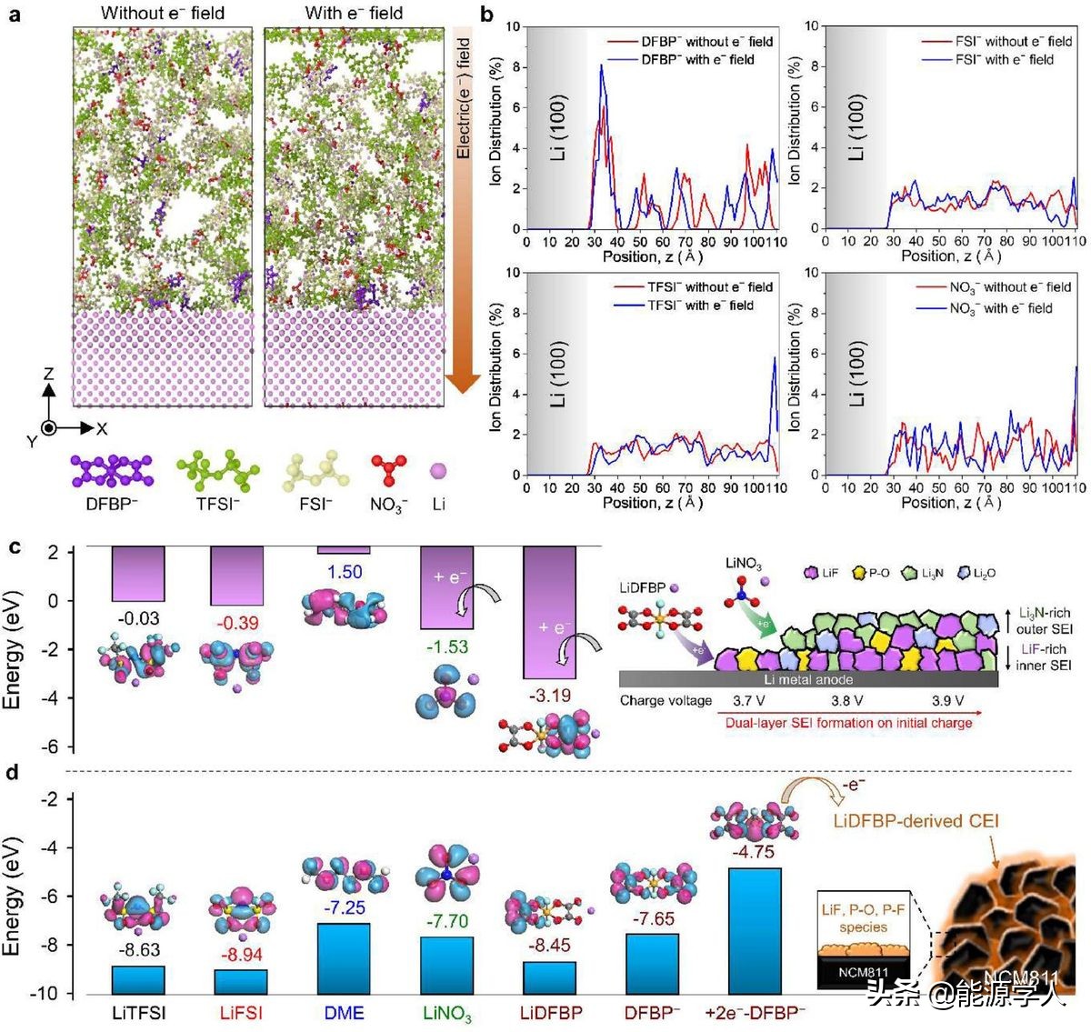
Figure 1. a) Snapshot of the lithium metal-anode-electrolyte interface system without (left) and (right) electric fields; b) the ion distribution of each anion in the z direction. c, d) HOMO-LUMO energy level diagrams of the studied salt, solvent and ionic additives. c) LUMO and d) HOMO energy diagrams of different substances.
2. Electrochemical performance of fluorine and nitrogen ion-donating additives in LMBs
Use Li|NCM811 full battery to check the electrochemical performance of (2M LiFSI+1M LiTFSI) DME+1% LiDFBP+3% LiNO3 (LiDFBP+LiNO3) electrolyte. The Li|NCM811 full battery using LiDFBP+LiNO3 shows a higher discharge capacity (200.1 mAh g-1), the initial coulombic efficiency (ICE) is as high as 90.8%, and the cycle performance is longer than that of carbonate+FEC electrolyte. It is worth noting that the cycle stability of the full battery is significantly improved after using LiDFBP+LiNO3 electrolyte, with a high CE of 99.94% in 600 cycles (Figure 2a, e). On the contrary, in the absence of additives, the discharge capacity and CE of the full battery are severely attenuated, and at the same time, the overcharge phenomenon is caused by the poor decomposition of LiFSI and DME at the cathode of NCM811 after 50 cycles (Figure 2b). Batteries prepared using LiDFBP related to the formation of SEI and CEI on both electrodes showed a significant decrease in discharge capacity and CE after 155 cycles. The full battery prepared with LiNO3, which is mainly used to promote the formation of SEI on the lithium metal negative electrode, has achieved excellent cycle performance of more than 400 cycles. The cyclability of Li|NCM811 full cells based on LiNO3 or LiDFBP shows that controlling SEI to reduce the formation of lithium dendrites is more critical than building CEI at the cathode (Figure 2c, d). Therefore, these findings indicate that the highly durable DME-based electrolyte combining LiDFBP and LiNO3 can form a stable interface layer on the electrode.
The cycle performance of the full battery was evaluated at 1 C and 25°C to explore the applicability of CEI and SEI formed by LiDFBP+LiNO3 to enhance the charge transfer on the cathode surface. Although the LiDFBP+LiNO3 electrolyte has a high viscosity, it still achieves an excellent cycle stability of 80% after 369 cycles. In addition, LiDFBP+LiNO3 enhances the fast charge-discharge performance (Figure 2g, h). In particular, the Li|NCM811 full battery containing LiDFBP+LiNO3 additives has excellent discharge capacity at high discharge rates without serious capacity degradation (Figure 2h). Compared with the previously reported results, the DME electrolyte containing 1% LiDFBP+3% LiNO3 (2 M LiFSI+1 M LiTFSI) clearly ensures the good cycle performance of LMBs. In order to further verify the effect of LiDFBP+LiNO3, the author evaluated the cycle performance of a 40 μm Li|NCM811 full battery containing LiDFBP+LiNO3 electrolyte (Figure 2i). In addition, LiDFBP+LiNO3 helps to overcome the poor oxidation stability of DME-based electrolytes under high charge cutoff conditions of 4.3 V and 4.4 V vs. Li/Li+ (Figure 2j). This is mainly because LiDFBP promotes the formation of CEI, which can significantly improve the cycle performance compared with the additive-free electrolyte. At the same time, the amount of LiDFBP and LiNO3 must be optimized to obtain the stable cycle performance of the Li|NCM811 full battery by stabilizing the interface between the lithium metal negative electrode and the NCM811 positive electrode. The best cycle performance is achieved in the ratio of 1% LiDFBP+3% LiNO3, because the double-layer SEI formed by the reduction decomposition of LiDFBP and LiNO3 inhibits the formation of dendritic lithium, while the oxidative decomposition of LiDFBP leads to the formation of CEI to relieve DME The structure of the NCM811 cathode in the base electrolyte is degraded.
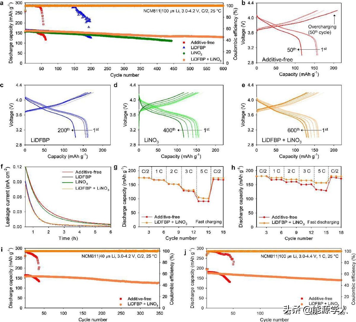
Figure 2. Electrochemical performance of Li|NCM811 full battery with no additives, containing LiDFBP, LiNO3 and LiDFBP+LiNO3 electrolyte. a) Cycle performance of Li|NCM811 full battery. The voltage curve of Li|NCM811 full battery, including b) no additives, c) LiDFBP, d) LiNO3 and e) LiDFBP+LiNO3 electrolyte. f) Electrochemical float test of Li|NCM811 full battery after 4.2 V vs. Li/Li+ pre-cycle. The rate performance of Li|NCM811 full battery with and without LiDFBP+LiNO3, g) a fixed discharge rate of C/2 and different charge rates and h) a fixed charge rate of C/2 and different discharge rates. The cycle performance of Li|NCM811 full battery, i) 40 μm Li metal negative electrode, from 3.0 V to 4.2 V, j) charge cut-off voltage is 4.4 V.
Minimizing the formation of dead lithium caused by the irreversible side reaction of the electrolyte during the cycle is essential to improve the cycling ability of LMBs. The formation of dead lithium can be suppressed so that a thin lithium metal negative electrode can be used to increase the energy density of LMBs. As shown in Figure 3a-c, the electrolyte without additives continuously reacts with the lithium metal negative electrode and produces a thick layer, which is mainly composed of dead lithium and insoluble by-products on the lithium metal negative electrode. At the same time, a large amount of it is consumed during the cycle. Natural lithium metal (Figure 3a-c). In contrast, the LiDFBP+LiNO3 electrolyte produced a double SEI structure, including an SEI layer derived from LiDFBP on the inside and LiNO3 on the outside, while retaining about 98 μm of fresh lithium metal after 50 cycles (Figure 3d-f). This finding is consistent with the results obtained by the stable cycle performance of the Li|NCM811 full battery using a foil-type lithium metal anode (40 μm) in the LiDFBP+LiNO3 electrolyte (Figure 2i).
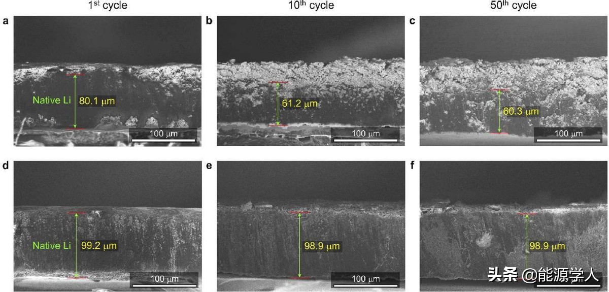
Figure 3. After cycling 1, 10, and 50 times at C/2 and 25°C, the Li|NCM811 full battery uses ac) no additives and df) LiDFBP+LiNO3 additive electrolyte after cycling the lithium metal negative electrode. Cross-sectional SEM image.
3. Electrochemical performance of the prepared electrolyte in Li|Cu and Li|Li symmetric batteries
The author uses Li|Cu and Li|Li symmetrical battery configurations to verify the electrochemical reversibility of lithium metal with different electrolytes. The ICE values of electrolytes containing LiNO3 and LiDFBP+LiNO3 were 92.1% and 93.0%, respectively, while the ICE values of electrolytes without additives and containing LiDFBP were relatively low, 39.8% and 82.7%, respectively (Figure 4a). The LiDFBP+LiNO3 electrolyte clearly showed a high average CE exceeding 99% during 350 cycles (Figure 4b). The Li|Li battery was tested in cycles to study the role of LiNO3 and LiDFBP additives in the stability of the Li metal anode interface (Figure 4c-f). The overpotential of the Li|Li battery with LiDFBP+LiNO3 is less than 100 mV, and the charge and discharge lasts for about 2700 hours (equivalent to 724 cycles), while maintaining stable lithium electroplating and stripping reactions (Figure 4f). However, due to the corrosion of lithium metal, the battery containing LiDFBP and LiNO3 without additives showed a large overpotential, resulting in poor cycle performance (Figure 4c-e). This means that the combination of LiDFBP and LiNO3 can construct an ideal SEI to improve the electrochemical reversibility of the lithium metal anode. Therefore, the interface engineering of NCM811 positive electrode and lithium metal negative electrode using dual-ion additives (LiDFBP and LiNO3) is essential to achieve high-performance LMB.
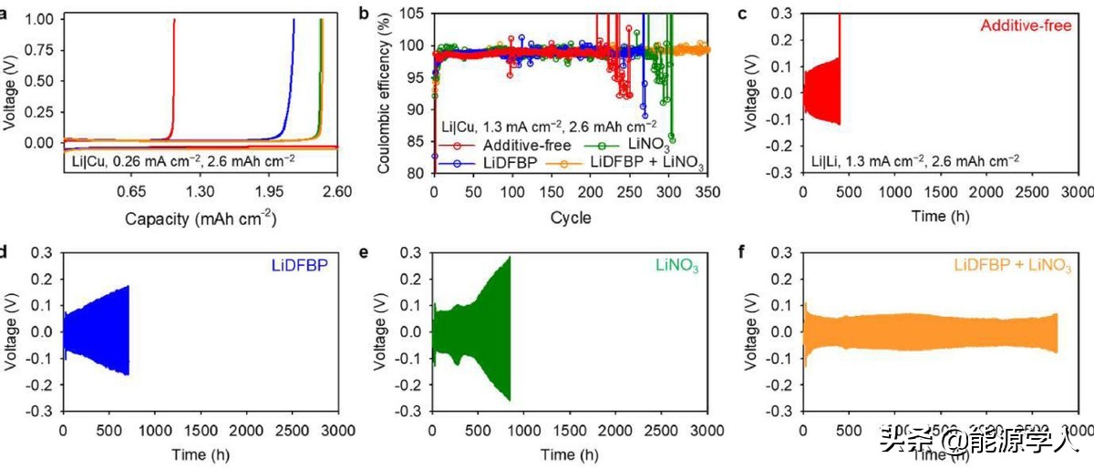
Figure 4. Electrochemical characteristics of Li|Cu battery and Li|Li symmetric battery. a) Initial Li electroplating/stripping voltage curve in Li|Cu battery and b) Coulombic efficiency profile of Li|Cu battery with no additives, containing LiDFBP, containing LiNO3 and containing LiDFBP+LiNO3 electrolyte. The voltage curve of a Li|Li battery with c) no additives, d) containing LiDFBP, e) containing LiNO3 and f) containing LiDFBP+LiNO3 electrolyte at 25°C.
4. Confirmation of double-layer SEI for protecting lithium metal anode
In-depth analysis using TOF-SIMS and ex-situ XPS confirmed the SEI structure formed by the combination of LiDFBP and LiNO3. From the outer (0 s, black) to the inner (960 s, pink) SEI layer (Figure 5a, b), the intensity of the Li3N peak (398.9 eV) in the entire SEI did not change significantly. The LiF signal at 685 eV is closer to the lithium metal negative electrode, indicating that the internal SEI contains a relatively large proportion of LiF. The external SEI is mainly composed of Li3N-rich regions (Figure 5a-c). Based on these results, it was confirmed that LiDFBP had a significant contribution to the formation of internal SEI, and it was found that the external SEI contained Li3N-rich regions produced by LiNO3 decomposition, and SEI components derived from LiDFBP. Figure 5d provides further evidence for the construction of a double-layer SEI on the lithium metal negative electrode. A strong signal corresponding to LiF- was found in the inner layer of the SEI, and the intensity of the LiN- signal remained constant in the entire SEI layer of the standardized TOF-SIMS depth profile. A higher proportion of C2HO-, CHO2-, and NH-substances were observed in the middle SEI layer, while a relatively larger proportion of SO- and SF-substances appeared in the outer SEI. The polar parts (PO and PF) near the outer SEI layer will interact with Li+ ions through ion-dipole interactions, thereby achieving rapid Li+ ion transport through the SEI layer. In general, the LiNO3-derived outer SEI layer cannot withstand the extreme volume changes of lithium metal and can be used as a fast Li+-ion transport medium, while the LiDFBP additive increases the LiF content in the inner SEI layer, which helps to inhibit the formation and formation of lithium dendrites. SEI’s mechanical degradation.
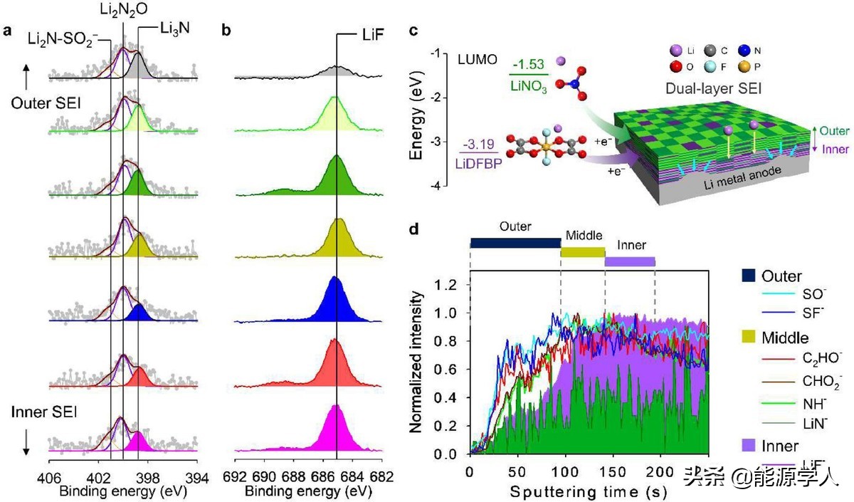
Figure 5. Surface chemistry of lithium metal negative electrode recovered from Li|NCM811 full battery using LiDFBP+LiNO3 electrolyte cycle. In-depth analysis of a) N1s and b) F1s XPS of lithium metal anode after pre-cycle at 25°C. c) Schematic diagram of LiDFBP+LiNO3 electrolyte forming a double-layer SEI layer. d) After 20 cycles at C/2, use LiDFBP+LiNO3 electrolyte to perform TOF-SIMS 3D depth analysis on the double-layer SEI layer on the lithium metal negative electrode.
5. LiDFBP improves the structural stability of NCM811 cathode
LiDFBP can promote the formation of CEI and help maintain the interface durability of the NCM811 positive electrode, which was confirmed by ex-situ XPS analysis of the positive electrode pre-circulated in LiDFBP+LiNO3 and LiDFBP electrolytes (Figure 6a-d). Corresponding to the peaks of 134.2 eV of PO and 136.8 eV of PF species, these peaks appear in the spectra of the positive electrode pre-circulated with LiDFBP+LiNO3 and LiDFBP (Figure 6a, b). In addition, the presence of a strong signal representing the PVDF binder at 687.9 eV indicates that the CEI layer in LiDFBP+LiNO3 is relatively thin compared to that obtained in the additive-free electrolyte (Figure 6c, d). TOF-SIMS analysis was performed to further clarify the origin of this thin CEI in LiDFBP+LiNO3. Unlike the additive-free electrolyte that showed strong SF- and LiF2- signals during LiFSI decomposition, the cathodes pre-circulated in LiDFBP+LiNO3 observed significantly weak SF- and LiF2- signals (Figure 6e, f). Importantly, the strong PO2− signal detected for the NCM811 cathode with LiDFBP + LiNO3 means that LiDFBP mainly contributes to the construction of CEI (Figure 6e, f). This result is consistent with the normalized depth profile (Figure 6g, h). LiDFBP+LiNO3 electrolyte significantly reduces the thickness of CEI on the cathode of NCM811.
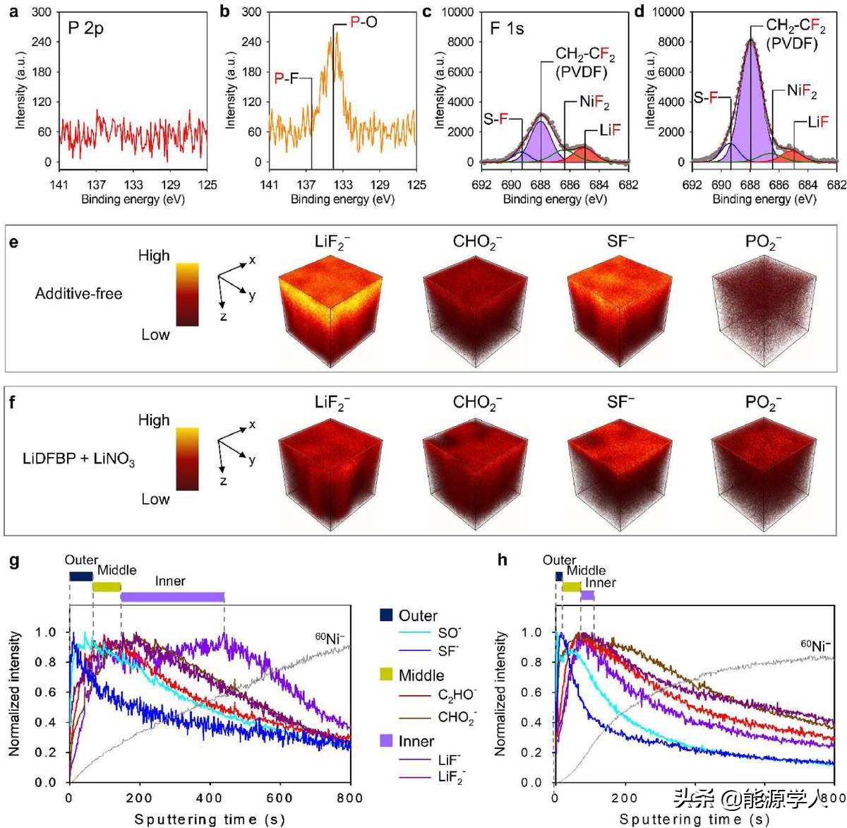
Figure 6. Surface chemistry of NCM811 positive electrode recovered from Li|NCM811 full battery with and without LiDFBP+LiNO3 pre-cycled. P 2p XPS profile view, F 1s XPS profile view, TOF-SIMS 3D stereo image and depth profile view of NCM811 cathode. Among them, a, c, e, g) contain no LiDFBP+LiNO3, and b, d, f, h) contain LiDFBP+LiNO3.
The HR-TEM image and the corresponding fast Fourier transform (FFT) mode revealed the positive influence of LiDFBP+LiNO3 electrolyte on the microstructure of the NCM811 cathode (Figure 7). The FFT mode reveals that there is a rock salt facies at point A, a mixture of rock salt facies and stratified facies at point B, and a stratified facies at point C. It is worth noting that the use of LiDFBP+LiNO3 reduced the thickness of the rock salt phase from 5.76 nm to 3.71 nm, indicating that the LiDFBP-derived CEI remained stable during 60 cycles at 25°C, effectively inhibiting the mixing of Ni/Li cations. The phase transition from layered to rock salt facies (Figure 7a-d). The phase change of the NCM811 cathode can be explained by electron energy loss spectroscopy, which is used to determine the electronic structure of the NCM811 cathode based on the oxidation state of TM ions. A series of OK-, Co L- and Ni L- edge peaks were obtained from the surface to the body (30 nm from the surface) at 3 nm intervals in each scan (Figure 7e-h). According to the amount of oxygen loss, the OK edge is associated with the valence state of the TM ion. The width of the OK edge peak of the NCM811 cathode with LiDFBP+LiNO3 is reduced, and the offset from 528 eV to higher energy is reduced (Figure 7e, g). This indicates that TM ions are reduced by 3d hybridization, thereby reducing the transition of electrons from O 1s to O 2p state. In addition, a clear OK edge peak began to appear 9-12 nm below the surface of the NCM811 cathode without LiDFBP+LiNO3 cycles, while the OK edge peak of the cathode containing LiDFBP+LiNO3 was only 3-6 nm deep from the surface. At the same time, in the cathode containing LiDFBP+LiNO3 electrolyte cycle, the intensity of the edge peaks of OK-, Ni L- and Co L- increased (Figure 7e-h). This means that the LiDFBP-derived CEI not only inhibits the unnecessary oxidation of the DME-based electrolyte on the NCM811 positive electrode, but also inhibits the structural degradation of the positive electrode. In addition, the energy dispersive X-ray spectrum scan from the surface to the body of the cathode without LiDFBP+LiNO3 shows a relatively high F intensity, which is attributed to the thick CEI layer composed of LiF and SF produced by the decomposition of LiFSI+LiTFSI (Figure 7i,j).
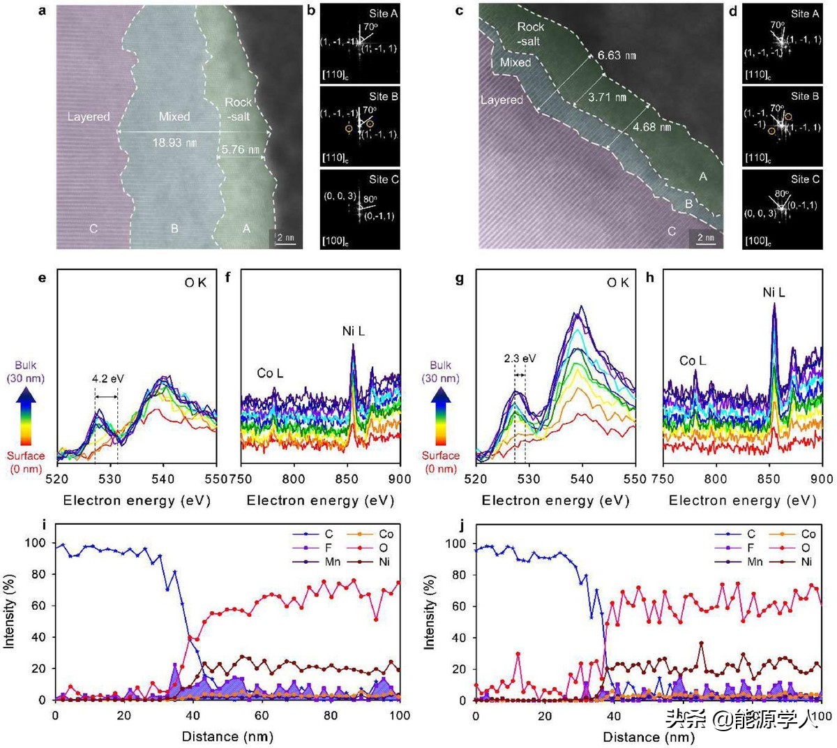
Figure 7. Structural characteristics of NCM811 positive electrodes recovered from Li|NCM811 full batteries with and without LiDFBP+LiNO3 electrolyte after 60 cycles at C/2 and 25°C. HR-TEM image and corresponding FFT analysis of NCM811 positive electrode a, b) does not contain LiDFBP+LiNO3 and c, d) contains LiDFBP+LiNO3. FFT images of rock salt (point A), mixed phase (point B), and layered (point C) structures are also displayed. A series of EELS O K-, Co L- and Ni L- edge spectra obtained from the surface to the inside of the NCM811 cathode (30 nm), where e, f) do not contain LiDFBP+LiNO3 and g, h) contain LiDFBP+LiNO3. Linear EDS scanning of the cathode after cycling from the surface to the inside, i) without LiDFBP+LiNO3 and j) containing LiDFBP+LiNO3.
[Summarize]
The author demonstrated an additive combination of LiDFBP as an F donor and LiNO3 as an N donor to create a stable interface layer on the NCM811 positive electrode and lithium metal negative electrode to develop high-performance LMB. The additive-free electrolyte exhibits poor cycle performance (50 cycles) at a capacity retention rate of 80%, and produces a large amount of by-products during the cycle. The results of this study reveal the importance of the order in the SEI structure for the electrochemical reversibility of the lithium metal anode to obtain the stable cycle performance of LMB (the capacity retention rate of 600 cycles is 80.9%). The internal SEI layer derived from LiDFBP acts as a physical barrier to support the mechanical durability of the internal SEI. The active intermediate derived from the electrochemical reduction of LiDFBP with high electron affinity triggers the outer SEI layer derived from LiNO3, which is conducive to the transfer of lithium ions. In addition, LiDFBP can construct CEI to ensure that DME-based electrolytes that are susceptible to highly oxidizing environments are electrochemically stable on the NCM811 cathode. This study provides an in-depth understanding of the development of reactive additives and the double-layer SEI structure on the surface of lithium metal anodes, and also proves the necessity of ion-conducting CEI to prevent the degradation of nickel-rich cathode structures.
More information: Saehun Kim et al, Stable electrode–electrolyte interfaces constructed by fluorine- and nitrogen-donating ionic additives for high-performance lithium metal batteries, Energy Storage Materials (2021). DOI: 10.1016/j.ensm.2021.10.031


