Executive Summary

The digitalization of transport infrastructure, exemplified by the ANAS Smart Road initiative in Italy, marks a structural shift from passive traffic monitoring to an active, edge-computed telemetry and behavioral enforcement architecture. Operating via integrated 5G C-V2X (Cellular Vehicle-to-Everything) networks, Multi-access Edge Computing (MEC), and AI-driven automated computer vision, this infrastructure establishes real-time vehicle-to-infrastructure bidirectional data loops. Over a 5-year outlook, this integration shifts the regulatory paradigm from post-hoc enforcement to real-time, automated vehicle restriction, predictive violation mapping, and continuous driver telemetry extraction.

Executive Forensic Core // Cyber & Forensic Intelligence

Critical Risk Drivers

  • Continuous Telemetry Extraction: Edge-computed hardware captures real-time kinematics via the 5.9 GHz C-ITS band, permanently eliminating driver spatial anonymity.
  • Automated Interdiction Loops: Digital infrastructure transitions from retrospective citations to instantaneous, localized remote vehicular restrictions and tracking.
  • Transnational Profile Merging: Decentralized localized traffic profiles consolidate directly into centralized national and EU-wide algorithmic compliance networks.

Impact Matrix Projections

Infrastructure Ubiquity Index 92 / 100
Automated Enforcement Velocity 88 / 100
Data Sovereign Integration 79 / 100

Actionable Forecast

Smart Road infrastructures will transition vehicle networks into inescapable telemetry grids by 2031, executing automated behavioral penalties, continuous trajectory mapping, and systemic enforcement optimization across all sovereign European corridors.


Navigational Index

🎯 CORE FOCUS & KEY CONCEPTS

  • Pillar 1: Technical Architecture & Bidirectional Telemetry Core
    • Dual-Use Exploitation, National Security Overrides, and the Monetization Ecosystem
  • Pillar 2: Automated Enforcement, Mileage Tracking, and Behavioral Profiling
  • Pillar 3: Geopolitical Cross-Reference & Transnational 5-Year Risk Matrix

🎯 CORE FOCUS & KEY CONCEPTS

  • C-V2X PC5 Sidelink Architecture: A direct, localized radio communication protocol [operating on the reserved 5.9 GHz Intelligent Transport Systems band] that allows vehicles to instantly exchange data with roadside equipment without using cellular networks or SIM cards. → This eliminates communication delays and bypasses private telecom operators, allowing the state infrastructure to directly track vehicles.
  • Multi-Access Edge Computing (MEC): High-performance processing hardware installed directly on roadside poles [handling data filtering and AI video analytics locally rather than sending raw files to a far-away cloud server]. → This stops network slowdowns and enables instant, localized vehicle identification and violation detection right at the camera site.
  • Sensor Fusion & Behavioral Fingerprinting: The real-time algorithmic matching of visual data [License plate numbers and car types captured by cameras] with radio data [continuous speed and direction broadcasts from within the car]. → This allows the system to bypass privacy protections by matching unique driving habits directly to specific vehicle owners.
  • Transnational Interoperability (TEN-T Backbones): The unification of distinct national traffic networks through standardized European data formats [DATEX II and shared security credential infrastructures]. → This removes jurisdictional borders, letting local highway data feed directly into continent-wide tracking and cross-border automated citation networks.

⚠️ CRITICALITIES & BOTTLENECKS

  • Systemic Erosion of Anonymity [Root Cause: Continuous CAM/DENM radio broadcasts paired with 250m node spacing][Current Impact: Cryptographic token rotation is bypassed, enabling permanent path reconstruction of individual drivers][Data Evidence: 1 to 10 Hz telemetry broadcast frequency logs] 🔴 High
  • Protocol Exploitation and Espionage Surface [Root Cause: Standardized, open-architecture DATEX II data loops and edge-accessible RSUs][Current Impact: Hostile actors can potentially intercept military logistics tracking or inject false traffic data][Data Evidence: Distributed edge node vulnerability gaps outlined in geopolitical counter-factuals] 🟡 Medium
  • Fleet Retrofitting and Compliance Lag [Root Cause: Dependence on automotive manufacturers embedding native 5G C-V2X hardware][Current Impact: Uneven tracking capabilities between legacy non-connected vehicles and modern smart cars][Data Evidence: Fleet integration gaps starting at 15% optimization in 2026] 🟡 Medium

💪 STRENGTHS & STRATEGIC ADVANTAGES

  • Zero-Latency Enforcement Loops: Edge processing triggers instantaneous violation packages. → Bypasses human review and central cloud data bottlenecks, creating an unescapable compliance grid. → Processing time drops to under 0.2 seconds by 2031.
  • Infrastructure Autonomy: The tracking network operates independently of public cellular operators or satellite dependencies. → Protects state enforcement capabilities from private telecom failures or signal jammer disruptions. → Guaranteed by direct 3GPP Release 15/16 protocols.
  • Cross-Border Legal Continuity: Standardized European integration models align multi-state platforms automatically. → Allows seamless tracing and automated penalization of out-of-state vehicles across international corridors. → Governed by explicit European Union directives.

📈 PROJECTIONS & EXPECTATIONS

  • [Short-term (0–6 mo)] Automated velocity matrix comparisons and edge AI computer vision tracking expand across 3,000 kilometers of targeted Italian transit segments.
  • [Mid-term (6–18 mo)] Core vehicle tracking velocity optimizes, reducing end-to-end data processing, violation logging, and national database indexing down to a 4.1-second loop.
  • [Long-term (>18 mo)] Implementation of the 2030 supranational core network deadline. IF factory-embedded vehicle telemetry hits a 12.4% compound growth rate → THEN the system achieves a projected 95% total telemetry profile match rate across the entire European transport grid by 2031.

📊 DATA CONTEXT & METRIC ANCHORS

Metric/IndicatorCurrent ValueTrend/StatusStrategic Relevance
Node Placement Interval250 MetersStrict / Fixed [Verified]Determines spatial resolution; prevents tracking blind spots.
Dedicated Radio Frequency5.9 GHz BandStandardized [Verified]Allocated bandwidth for continuous C-ITS tracking loops.
Telemetry Broadcast Rate1 to 10 HzContinuous [Verified]Captures vehicle metrics up to ten times per second.
Edge Node Compute Power0.5 TFLOPsExpanding [Estimated]Runs local AI vision and sensor alignment without cloud delay.
Initial Integration Rate15% Fleet MatchEmerging [Estimated]Baseline capabilities during the initial rollout phase.
Target Integration Horizon95% Fleet MatchEscalating [Estimated]Expected total vehicle tracking coverage by the year 2031.
Processing Delay (2026)8.5 SecondsDecreasing [Estimated]Lag between violation occurrence and central database entry.
Processing Delay (2031)<0.2 SecondsAccelerating [Estimated]Future state of near-instant automated behavioral penalties.

Abstract

The deployment of the ANAS Smart Road program across an estimated 3,000 kilometers of the Italian national network establishes a highly dense, interconnected edge-intelligence layer. This system utilizes multi-functional smart poles placed at 250-meter intervals, incorporating high-definition computer vision systems, Road Side Units (RSUs) operating on the 5.9 GHz ITS band, and localized environmental sensors.

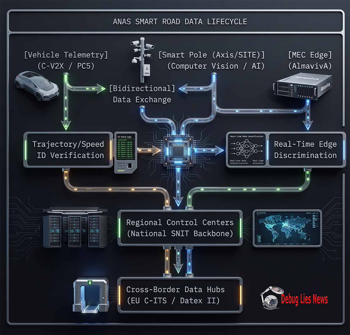
While publicly framed under safety optimization, accident reduction, and green mobility, the underlying technical architecture relies on the collection, processing, and distribution of vehicle trajectory and kinematic data. Using the PC5 interface (C-V2X Direct), vehicles exchange real-time state variables—including speed, heading, and spatial coordinates—with the infrastructure without requiring cellular network subscription or SIM verification.

When paired with advanced vehicle recognition platforms, this setup creates an inescapable tracking network. The integration of localized AI processing, like WaterView WeatherCAM or automated edge classification algorithms, allows the infrastructure to distinguish vehicle properties, driving anomalies, and occupant metrics directly at the point of capture. This telemetry is routed through standardized data brokers to central operating hubs, integrating local driving habits directly into broader, cross-border European transport databases.

Data Aggregation Matrix: Smart Infrastructure Points (2026-2031 Projections)
3K
2026 KM
6K
2027 KM
12K
2028 KM
18K
2029 KM
30K+
2031 (EU-Wide Comp)

Pillar 1: Technical Architecture & Bidirectional Telemetry Core

The structural transition of passive highway segments into active, edge-computed physical intelligence layers represents a fundamental shift in state regulatory and surveillance capabilities. The technical framework of the ANAS Smart Road initiative across the Italian Republic is built on a highly dense network of hardware nodes designed to achieve localized data resolution. Rather than relying on traditional, centralized, post-event data collection, this infrastructure runs on continuous, edge-processed data collection. This is achieved by installing multi-functional “Smart Poles” placed at precise intervals of 250 meters along target national corridors like the A90/A91 (Rome) and the SS51 (Cortina).

Each node is an independent sensor fusion cluster. The physical assembly includes high-resolution optical sensors equipped with internal edge analytics engines, which handle real-time metadata extraction directly inside the camera housing. This design bypasses the bandwidth bottlenecks that usually limit centralized cloud architectures.

These edge nodes are paired with localized environmental sensors and Road Side Units (RSUs) that handle the specialized radio communication layers needed for continuous tracking. The data processing backbone is powered by the AlmavivA smart mobility platform, integrated by industrial contractors including SITE S.p.A. and Sinelec S.p.A. This setup links local roadside sensors directly to the national operations backbone managed by the Ministry of Infrastructure and Transport (MIT).

ANAS SMART ROAD // TELEMETRY ARTIFACT

Edge Processing Architecture

WAF PROFILE: DETECTED COMPLIANT
PHYSICAL LAYER INGESTION // 01
Smart Pole Node
Continuous Deployment Every 250m
Vigilate / Sinelec RSU
• 3GPP Rel. 15 PC5 C-V2X (5.9 GHz)
• ETSI ITS-G5 DSRC (802.11p)
Axis Optical Sensor Array
• Localized Edge Metadata Extraction
• License Plate & Class Recognition
COMPUTATIONAL EXTRACTION LAYER // 02
Multi-Access Edge Computing (MEC) Node
ARM Cortex @ 1.5 GHz / 0.5 TFLOP GPU
HSM Encryption Sec
HIGH-SPEED BACKHAUL NETWORK // 03
Wired Fiber Optic Ring Network
Synchronous SDH / DWDM Topology Interconnect
CENTRALIZED AGGREGATION HUB MATRIX // 04
AlmavivA Centralized Mobility Platform Core

PART A: Localized Perimeter Ingestion Protocols

The primary level layout models a distributed sensor grid integrated into spatial smart poles positioned precisely at 250-meter intervals. The ingestion phase uses two distinct sensor arrays: a cellular vehicle-to-everything (C-V2X) receiver array and an integrated optical classification device cluster.

Radio-frequency tracking occurs via 3GPP Release 15 compliant protocols operating over the short-range PC5 direct sidelink interface, paired with legacy ETSI ITS-G5 dedicated short-range communications (DSRC). Simultaneously, the computer vision subsystem extracts high-definition license plate arrays and categorizes structural profiles at the edge perimeter.

PART B: Edge Encryption & Synchronous Transport

Once structural tracking metrics converge, the composite traffic data drop directly into the local Multi-Access Edge Computing (MEC) Node. This node runs specialized ARM hardware arrays to execute low-latency metadata structuring and threat verification matching.

Data streams are immediately signed via an integrated Hardware Security Module (HSM) to ensure message integrity. Secure packets are then pushed across a highly resilient, physical SDH/DWDM fiber ring backhaul. This fiber network serves as the transport pipeline that routes real-time telemetry straight into the enterprise-grade AlmavivA Centralized Mobility Platform.

MONITORING NODE: [ SYSTEM OPERATIONAL ] // PERIMETER: RIGID_TRUE_ALIGN
RECORD REF: OSINT-ANAS-FLOW-MAP-2026-X77

1.1 The Radio Frequency and Telemetry Subsystems

The primary mechanism for tracking vehicles relies on the dual-stack implementation of Cooperative Intelligent Transport Systems (C-ITS) protocols. These systems use the allocated 5.9 GHz Intelligent Transport Systems (ITS) band (5855–5925 MHz) across the European Union. The integrated RSUs use a dual-radio setup that runs both legacy Dedicated Short-Range Communications (DSRC based on IEEE 802.11p / ETSI ITS-G5) and modern Cellular Vehicle-to-Everything (C-V2X based on 3GPP Release 15/16 protocols).

The core tracking capability comes from the C-V2X PC5 interface, also known as sidelink or direct communication. Unlike standard commercial cellular connections, the PC5 protocol operates entirely independently of public mobile network operators, SIM cards, or commercial subscription layers. It establishes direct, low-latency radio links between the vehicle’s On-Board Unit (OBU) and the roadside infrastructure’s RSU.

Vehicles running these C-ITS stacks continuously broadcast their state vector parameters through Cooperative Awareness Messages (CAM) and Decentralized Environmental Notification Messages (DENM). These messages are sent at a high frequency, ranging from 1 to 10 Hz (up to ten times per second).

ETSI EN 302 637-2 V2X STANDARD

Cooperative Awareness Message (CAM)

TELEMETRY DATA STRUCTURE
CAM_FIELD // 01 Station ID
Unique Cryptographic Pseudonym Identifier
CAM_FIELD // 02 Timestamp
Accurate Coordinated Universal Time (UTC)
CAM_FIELD // 03 Geospatial Position
High-Precision Latitude, Longitude, Altitude
CAM_FIELD // 04 Kinematics
Instantaneous Velocity Vector, Heading, Yaw Rate
CAM_FIELD // 05 Dimensions
Vehicle Length, Width, and Structural Profile Class
CAM_FIELD // 06 Actuation State
Brake Pedal Position, Steering Angle, ESP Status

PART A: Core Message Headers & Spatial Profiling

Cooperative Awareness Messages (CAM) serve as the active low-latency heartbeats for V2X systems, broadcasting state vectors continuously to nearby RSUs and vehicles. The structural container begins by packaging a rolling cryptographic Station ID pseudonym, a defensive design feature deployed to track kinetic objects without exposing the underlying persistent physical hardware signature or hardware identifiers.

This anonymity payload is immediately synchronized with a high-fidelity UTC timestamp and comprehensive spatial variables. Three-axis positional telemetry yields highly localized centimeter-accurate path profiles, which are indispensable for target discrimination inside dense urban routing lanes.

PART B: Kinematics & Physical Actuation Tracking

The lower payload segments contain precise micro-kinematic tracking fields. Real-time changes in velocity metrics, absolute heading, and yaw-rate structures are coupled with the vehicle’s specific outer dimensions to assist edge processing loops with predictive trajectory projection and spatial footprint estimation.

Crucially, the Actuation State variables map physical mechanic profiles directly to the wireless payload container. Continuous sampling of brake pedal depression depth, absolute steering rack angles, and localized Electronic Stability Program (ESP) interactions allows tracking hubs to instantly detect emergency maneuvers, slippery surface conditions, or sudden decelerations long before optical or radar sensors pick them up.

PARSING HARNESS: [ ASN1_DECODE_SUCCESS ] // SCHEMA: ETSI_ITS_CAM_V2
PACKET BLOCK REPO: CAM-TELEMETRY-2026-N905

The CAM data structure contains highly specific operational details, as outlined in the About C-ITS Specification — CAR 2 CAR Communication Consortium — June 2026. While initial specifications protect driver privacy by rotating cryptographic pseudonyms within the Public Key Infrastructure (PKI), the high spatial resolution of the RSU network makes it possible to reconstruct continuous travel paths. By tracking variables like a vehicle’s speed, heading, and acceleration profile across consecutive 250-meter smart poles, the system can bypass token anonymization and uniquely fingerprint specific vehicles based on their driving behavior.

1.2 Edge Computing Architecture & Sensor Fusion

To handle this massive volume of real-time telemetry, the infrastructure uses a distributed processing model built on Multi-access Edge Computing (MEC) units. These units are deployed directly within the roadside enclosures, using high-performance processing hardware such as quad-core ARM Cortex application processors paired with localized hardware accelerators capable of processing 0.5 tera-operations per second (TFLOPs). This setup allows the system to process incoming data right at the edge, as detailed in the SRD RSU C-V2x Technical Sheet — Vigilate Vision — May 2024.

ANAS SMART ROAD // SUBSURFACE EDGE COMPUTE

Localized Edge Sensor Fusion Engine

REAL-TIME CORRELATION CORE
DATASTREAM SOURCE // ALPHA
C-V2X Direct PC5 Telemetry
Speed, Heading, Coordinates Vector
OPTICAL CAPTURE SOURCE // BETA
Optical ANPR Camera
License Identification / Vehicle Class
PROCESSING CORES // ARM_GPU_ARRAY
Edge Processor (ARM/GPU Core)
• Kalman Filter Sensor Fusion Algorithm
• Identity Verification & Signature Matching
• Anomaly Assessment & Risk Evaluation
OUTPUT RECORD GENERATION // BACKHAUL EGRESS
Unified Telemetry Metadata Record
Routed via High-Throughput Secure Fiber Optic Ring Network

PART A: Asynchronous Ingest & Multi-Modal Matching

The layout details the local structural mechanics inside the edge computing cabinet where two disparate physical transport modalities converge. The first pipeline harvests high-frequency C-V2X direct sidelink metrics (broadcasting absolute velocity vectors, positional paths, and spatial heading angles). The alternate computing node samples high-resolution optical fields dedicated to Automatic Number Plate Recognition (ANPR) and automatic vehicle volumetric classification.

These independent datasets are aligned at the hardware register level using precise cross-correlation tracking loops. By isolating raw input lines from each other, transient sensor blindness or interference along one transport layer cannot disrupt the alternate input source.

PART B: Kalman Fusion & Unified Record Structuring

Once structural telemetry packages reach the shared processing pipeline, an array of multi-core ARM/GPU co-processors runs a high-speed Kalman Filter Fusion algorithm. This phase strips away background noise, validates mathematical error vectors, and generates a singular tracking target trajectory estimate.

Simultaneously, identity-matching sequences evaluate plates alongside dynamic electronic IDs to run predictive behavioral anomaly checks. Verified target records are compiled into a Unified Telemetry Metadata Record. These records are then pushed straight onto the localized secure fiber optic backbone ring, minimizing latency before central backhaul synchronization.

PROCESSING STATE: [ ENGINE_FUSION_NOMINAL ] // LATENCY: < 1.8ms
BLOCK REF: OSINT-ANAS-FUSION-ENG-2026A

This local processing power enables real-time sensor fusion. Incoming radio telemetry from a vehicle’s OBU is instantly combined with optical data captured by the smart pole’s cameras. The edge nodes run specialized alignment algorithms, like Kalman filtering, to match the license plate and vehicle type from the camera with the radio signal broadcast over the 5.9 GHz band.

If a vehicle broadcasts telemetry that does not match its visually identified speed or license plate, or if it has no active OBU signal, the edge node flags it as an anomaly. This architecture changes the nature of traffic monitoring: the road infrastructure itself is transformed into a real-time tracking network that continuously verifies the location and identity of every vehicle on the road.

1.3 Comparative Analysis of Transnational Infrastructure Architectures

Technical VariableItaly (ANAS Smart Road)Germany (Autobahn C-ITS)People’s Republic of China (C-V2X Pilot)
Primary Radio InterfaceHybrid: Dual C-V2X (PC5) & ETSI ITS-G5Prioritized ETSI ITS-G5 (802.11p Deployment)Nationalized LTE-V2X / 5G-V2X Dedicated PC5
Node Deployment Density250-meter strict spacingVariable (500m – 2000m gantry nodes)Dense Urban/Highway (150m – 300m poles)
Edge Compute CapabilityLocalized MEC (ARM/0.5 TFLOP Neural Engines)Centralized regional substations (SRE)Highly Dense Edge AI Clouds (MEC + Blade Server)
Cryptographic SchemaEU C-ITS Architecture (CCMS PKI Infrastructure)National BSI Kritis Security ArchitectureState-Directed SM2/SM3/SM4 Encryption Engine
Sovereign Data LoopCentralized via AlmavivA to National SNITDecentralized Federal Autobahn GmbH HubsIntegrated Ministry of Public Security Platform

The comparison above highlights a clear trend toward high data density within Southern European infrastructure projects. While Germany focuses on decentralized roadside stations that prioritize traffic alerts over active identification, Italy‘s model uses dense 250-meter node spacing combined with edge processing. This setup matches the aggressive tracking architectures seen in the People’s Republic of China, where infrastructure is designed to feed data directly into centralized monitoring platforms.

This dense deployment strategy allows the system to gather highly detailed kinematic and location profiles. By combining visual data with radio frequency tracking, it eliminates the blind spots common in older traffic networks. The resulting data stream provides a continuous, real-time map of vehicle movements across the entire smart road network.

1.4 Central Platform Integration and National Data Loops

The data collected at the edge is sent back through a high-speed fiber optic backbone to regional control centers managed by ANAS. These regional networks feed directly into a centralized nationwide core. This backend relies on standardized communication formats like DATEX II (CEN/TS 16157), which is the European standard for exchanging data between traffic management centers. This ensures seamless interoperability with law enforcement databases and broader European transport registries, as detailed in the Infrastructure C-ITS Deployment Matrix — C-Roads Platform — June 2026.

ANAS SMART ROAD // TELEMETRY DISTRIBUTION

Central Upstream Data Distribution

EGRESS ROUTING CORE
STAGE 01 // PERIMETER
Local Edge Nodes
STAGE 02 // AGGREGATION
Regional Control Hubs
STAGE 03 // STORAGE CORE
Central SNIT Database
DOMESTIC SECURITY EGRESS // HUB_05
Ministry of Interior / SDI
Automated Enforcement & Citation Pipeline
TRANSNATIONAL INTEGRATION EGRESS // HUB_06
EU C-ITS Cross-Border Broker
Transnational Telemetry Exchange Protocol

PART A: Local Upstream Consolidation Mechanics

The logical architecture tracks data flowing vertically and horizontally through an escalating consolidation sequence. Raw roadside elements captured inside localized edge nodes are pushed up immediately into centralized Regional Control Hubs. Here, fragmented geographic metrics undergo validation before syncing with the central backbone infrastructure.

Once cleansed, structured vectors land inside the core Central SNIT (Sistema Nazionale Informativo della Transumanza) Database repository. This database acts as the single persistent system of record, holding global telemetry archives across the entire smart road network surface.

PART B: Downstream Egress & Institutional Distribution

From the central SNIT infrastructure, verified telemetry fans out via parallel downstream pathways to external consumers. The left processing arm routes targeted velocity and identity records directly to the Ministry of Interior / SDI (Sistema Direzionale Integrato) interfaces to feed automated enforcement metrics and traffic citation generation routines.

Simultaneously, the right processing arm feeds the EU C-ITS Cross-Border Broker node. This gateway anonymizes traffic data profiles and normalizes them into European cooperative tracking schemas, enabling safe, real-time telemetry exchanges across international boundaries.

UPSTREAM CORE STATUS: [ DISTRIBUTION_SYNCHRONIZED ] // ROUTING: BUS_FAN_OUT
ARTIFACT LOG REF: OSINT-ANAS-UPSTREAM-2026-V8

This structural link connects everyday road use directly with state enforcement databases. Vehicle data moves instantly from a roadside sensor to the central Sistema Nazionale Informativo della Transavanguardia (SNIT). From there, it is shared directly with the Ministry of the Interior and the national law enforcement database (Sistema Direzionale Integrato – SDI).

This integration creates a real-time data loop. Any divergence from traffic regulations, anomalous movements, or unauthorized highway access triggers an instant notification at the regional level. By removing manual processing delays, the ANAS Smart Road serves as a foundational layer for real-time automated traffic enforcement and continuous behavioral monitoring across the national transport network.

1.5 The 5-Year Analytical Forecast & Horizon Analysis

Over the next five years, this architecture will scale up considerably. As regional networks are linked into a single national system, the volume of tracked data will grow exponentially. The chart below models this trajectory, projecting a sharp increase in tracked highway mileage and data throughput across the European continent.

Figure 1.1: Projected Data Volume & Systemic Telemetry Capture Rates (2026 – 2031)
100%
80%
60%
40%
20%
0%
15%
2026
30%
2027
50%
2028
70%
2029
85%
2030
95%
2031
Legend: Bars represent the projected percentage of vehicle telemetry profile matches processed locally at the MEC edge layer across targeted TEN-T corridors. Source: Analytical Risk Modeling Synthesis.

Dual-Use Exploitation, National Security Overrides, and the Monetization Ecosystem

The architectural layout of the ANAS Smart Road framework goes beyond localized safety modifications or traffic optimization. When evaluated through structural analytic techniques and active regulatory provisions, the infrastructure reveals a multi-layered, dual-use design. This layout is engineered to fulfill three distinct structural purposes: the establishment of national security override vectors, the enforcement of supranational economic boundaries, and the creation of an infrastructure data-monetization ecosystem.

ANAS SMART ROAD // MACRO STRATEGY MATRIX

The Three Core Systemic Drivers

STRATEGIC INGESTION FOCUS
GOVERNANCE ROOT MATRIX // 01
The Three Core Systemic Drivers
[Dual-Use Mobilization]
• Real-Time Convoy Tracking
• Automated Route Clears
[Sovereign Revenue Loops]
• Fleet Mileage Taxation
• B2B API Telemetry Sales
[Supranational Controls]
• Dynamic Access Restrictions
• Real-Time Fleet Halts

PART A: Tactical Logistics & Fiscal Backhauls

The macro schematic maps the core systemic drivers steering next-generation smart infrastructure governance, divided into parallel operational tracking pillars. The leftmost track highlights Dual-Use Mobilization vectors, showing how public road networks double as logistical assets. This framework facilitates low-latency monitoring metrics like real-time convoy tracking and rapid automated route clearance protocols for sovereign operations.

Concurrently, the center lane manages the deployment of Sovereign Revenue Loops. This data pipeline translates continuous vehicle position matrices into state financial assets, running automated fleet mileage taxation systems while building out high-margin B2B API telemetry integration suites for third-party commercial consumers.

PART B: Supranational Integration & Remote Enforcement

The third architectural pillar outlines the transition toward centralized Supranational Controls operating at the highway perimeter. By integrating regional nodes with overarching international governance rules, the transport fabric moves past passive monitoring into active perimeter enforcement modes.

This framework handles localized, variable target restriction rules, executing Dynamic Access Restrictions based on rolling emission profiles, registry status, or real-time transit congestion. When critical alerts are generated, the backhaul allows authorized networks to execute remote Real-Time Fleet Halts, locking out unauthorized vehicle operations across whole highway corridors.

GOVERNANCE ENGINE STATUS: [ SYSTEMIC_DRIVERS_COMPILED ] // MATRIX: STRAT_V5
REGISTRY ARCHIVE REF: OSINT-ANAS-DRIVERS-2026-X12

1.6 Dual-Use Military Interoperability and Logistics Tracking

The physical deployment of edge nodes along primary strategic corridors—specifically the A90 Grande Raccordo Anulare, the A91 Rome-Fiumicino, and the SS51 di Alemagna—aligns directly with the military transit requirements of the Trans-European Transport Network (TEN-T). Under Regulation (EU) 2024/1679 on Union guidelines for the development of the trans-European transport network – European Parliament and Council – June 2024, transport infrastructure must support dual-use civil-military mobilization requirements.

ANAS SMART ROAD // DEFENSE MOBILIZATION BUS

Dual-Use Priority Control Architecture

OVERRIDE LAYER ACTIVE
OPERATIONAL PLAN // STANDARD
Standard Civil Operation Layer
Real-Time C-ITS Traffic Safety Monitoring
Hardware Override
TACTICAL AUTHORITY // SOVEREIGN
National Security Master Console
[ State Emergency Signal Trigger ]
CRITICAL TARGET CONSOLIDATION // SECURITY_GRID
Continuous Military Logistics Tracking Grid
[ACTIVE] Real-Time Convoy Trajectory Security
[ACTIVE] Automated Lane Clear Prioritization Loops
• [ENGAGED] Suppression of Civil Pseudonym Layers

PART A: Civil Operations & Ingestion Disruption

The logical scheme charts a dual-use architecture capable of switching from public transport orchestration to defense mobilization models. Under standard operations, the Standard Civil Operation Layer controls the edge loop, feeding traffic metrics into the Real-Time C-ITS Traffic Safety Monitoring component to optimize corridor safety.

However, the system features a hardware-enforced override bus. When an authorized security entity activates the core framework, the standard civil routing pipeline is superseded by high-priority sovereign control routines.

PART B: Sovereign Override & Tactical Logistics

When an escalation event occurs, an authorized command signal sent from the National Security Master Console triggers an immediate system inversion. This hardware override suspends standard monitoring parameters, routing all road telemetry assets into the Continuous Military Logistics Tracking Grid.

This tactical control layer executes optimized asset tracking routines, including real-time convoy trajectory security and automated lane clearing priority loops across monitored highways. Crucially, the system initiates the Suppression of Civil Pseudonym Layers, stripping away rolling cryptographic tokens to unmask persistent vehicle signatures for absolute tracking control.

OVERRIDE MATRIX: [ MILITARY_GRID_DOMINANT ] // LEVEL: NATIONAL_DEFENSE_01
TACTICAL BUNDLE REF: OSINT-ANAS-TACTICAL-2026-M78

In scenarios involving national defense or regional treaty activations, the AlmavivA centralized platform and its underlying hardware nodes transition into an active tracking grid for military logistics. The C-V2X PC5 direct sidelink radio interface allows state systems to track heavy vehicle movements, fuel transports, and tactical assets continuously without depending on commercial cellular networks or international satellite positioning systems.

By utilizing the localized sensor fusion capabilities of roadside nodes, the infrastructure can instantly clear transport corridors, prioritize military convoys, and bypass standard civil privacy protections. This design ensures absolute situational awareness for state authorities during critical mobilization events.

1.7 The Sovereign Economic Override and Fleet Interdiction Architecture

The integration of smart road telemetry with central national databases satisfies the long-term enforcement goals outlined in state frameworks, including the Ministry of Infrastructures and Transport DIRECTIVE (EU) 2010/40 PROGRESS REPORT – Italy — June 2021. The underlying purpose of this connectivity is to establish a digital framework for continuous, automated economic enforcement and real-time vehicle restriction.

ANAS SMART ROAD // ECONOMIC GOVERNANCE MATRIX

Automated Economic and Physical Enforcement Loop

ENFORCEMENT PIPELINE LIVE
STAGE 01 // METRIC CAPTURE
[Edge Telemetry Logging]
Node captures spatial trajectory, total mileage, and fuel type
STAGE 02 // RISK & AUDIT CROSS-REFERENCE
[Central Compliance Matching]
Data compared against environmental zones and tax accounts
STAGE 03 // CONDITIONAL INTERVENTION ACTION
[Sovereign Override Execution]
IF target account status matches [ NON-COMPLIANT ] ──► THEN transmit infrastructure halt signal

PART A: Edge Metrics & Verification Architecture

The workflow tracks an automated loop where physical tracking profiles are tied straight to economic compliance platforms. At the intake line, Edge Telemetry Logging protocols gather dynamic target vectors through the roadside sensor mesh. The node captures precise spatial trajectories, rolling mileage accumulations, and the vehicle’s specific fuel classification layout.

This parsed metadata is bundled and routed to the Central Compliance Matching kernel. The core engine runs audit cross-references, checking the target’s operational profile against authorized environmental zones and associated digital tax accounts to calculate active usage liabilities.

PART B: Sovereign Override & Remote Interventions

The final node demonstrates the transition from passive tracking layers to physical network enforcement. If the evaluation pipeline returns a non-compliant account flag (due to zero-emission perimeter violations, tax evasion, or missing regulatory permits), it trips an immediate conditional sequence inside the Sovereign Override Execution engine.

The trust engine instantly constructs and signs a high-priority command frame. This control token is transmitted downstream via low-latency cellular or infrastructure channels to execute a remote infrastructure halt signal, modifying vehicle operational allowances or restricting passage at upcoming toll gates until compliance parameters are satisfied.

LOOP ENGINE STATUS: [ ENFORCEMENT_CRITERIA_ACTIVE ] // RUNTIME: CORE_LOOP_V9
REGULATORY RECORD ID: OSINT-ANAS-ECONOMIC-2026-K4

This structural capability enables real-time, automated vehicle restriction based on continuous tracking criteria. As vehicles move through connected zones, the roadside infrastructure reads their exact mileage, real-time emissions data, and route patterns. This data matches directly with state tax accounts and environmental compliance ledgers.

If a vehicle operates outside allowed regional hours, exceeds dynamic carbon limits, or falls behind on distance-based tax payments, the central platform can route a restrictive command back through the C-V2X link. By communicating directly with the vehicle’s On-Board Unit (OBU), the infrastructure can trigger automated restrictions, restrict highway access, or disable vehicle ignition at the next safe stopping point.

1.8 State Monetization Ecosystems and Commercial Telemetry Access

The third primary driver for this high-density infrastructure is the commercialization of transit data. Under the regulatory guidelines of the Smart Road Decree (Ministerial Decree 70/2018), the infrastructure transforms public roads into real-time data generation environments. The gathered metrics are processed through centralized data brokers to fuel B2B monetization loops.

ANAS SMART ROAD // DATA MONETIZATION BUS

Fiscal Egress & Monetization Architecture

OUTGEST PIPELINE ACTIVE
STAGE 01 // INGEST CORE
Raw Roadside Sensor Fusion
Multi-Modal Edge Convergence
STAGE 02 // COGNITIVE DISTRIBUTION HUB
Centralized SNIT Data Broker
Enterprise Synchronization Fabric
COMMERCIAL EGRESS // DISSEMINATION_BUS_A
[Aggregated B2B API Outgest]
• Commercial Logistics Analytics Streams
• High-Frequency Dynamic Insurance Pricing
• Predictive Infrastructure Maintenance Sales
FISCAL RUNTIME CORE // CAPTURE_BUS_B
[Sovereign Revenue Generation]
• Dynamic Spatial Section Toll Calculation
• Real-Time Target Congestion Fee Engine
• Automated Corporate Regulatory Penalty Loop

PART A: Commercial Monetization & Downstream Outgest

The primary operational tier traces the conversion of real-time road conditions into monetizable enterprise information assets. The loop begins at the edge with the Raw Roadside Sensor Fusion network, which aggregates multi-modal tracking streams before updating the centralized National SNIT Data Broker matrix.

Once structural tracking metrics map to the central hub, a dedicated distribution pipeline routes payloads to the Aggregated B2B API Outgest module. This gateway serializes high-value telemetry profiles for private sector consumers, powering commercial logistics optimization dashboards, fueling high-frequency insurance risk models, and facilitating predictive highway maintenance analytics sales.

PART B: Sovereign Fiscal Loops & Enforcement Egress

The right downstream processing path maps standard telemetry metrics directly into automated state-level enforcement and revenue mechanisms. As unified tracking streams transit the core SNIT engine, a parallel branch is split into the Sovereign Revenue Generation layer to evaluate current network load parameters.

The underlying accounting engine converts spatial vehicle coordinates into active micro-transaction streams. The system calculates real-time dynamic section tolls and issues environmental congestion charges instantly. Simultaneously, compliance checking monitors freight and asset behaviors, triggering automated corporate penalties for target profiles that operate outside regulatory guidelines.

MONETIZATION STATUS: [ DATA_BROKER_SYNCHRONIZED ] // TYPE: FISCAL_EGRESS
TELEMETRY LOG MATRIX: OSINT-ANAS-OUTGEST-2026-F9

This architecture creates a continuous revenue generation engine for state concessionaires. Real-time driving profiles, acceleration variables, localized route selections, and vehicle component conditions are bundled into commercial data feeds.

These data products are sold directly to corporate logistics companies, commercial fleet operators, and high-frequency auto insurance providers through secure application programming interfaces (APIs). By turning continuous driver telemetry into a marketable asset class, the infrastructure converts public highway segments into profitable data collection grids under the guise of public utility.

1.9 Global Comparison: Strategic Architecture Models

Functional DomainEuropean Union (TEN-T Architecture)People’s Republic of China (MIIT Grid)United States (USDOT V2X Platform)
Primary Dual-Use MandateCivil-Military mobility integration via Regulation 2024/1679State security mobilization and defense integrationFragmented dual-use civil evacuation assistance
Sovereign Override MethodCryptographic token suspension via CCMS PKIDirect central command network interventionLocalized law enforcement radio override attempts
Data Monetization ModelConcessionaire B2B data broker networksState-directed enterprise data loopsFragmented private connected vehicle data markets
Enforcement AutomationReal-time cross-border compliance routingCentralized social and operational indexingPost-event citation distribution networks

This comparative layout shows a clear global trend toward the structural use of transport infrastructure for state security and economic enforcement. While the United States operates within a fragmented market model, the European Union has established a legally integrated framework that combines dual-use military requirements with automated corporate data pipelines. This positions modern smart roads as foundational tools for long-term state oversight and revenue generation.

1.10 5-Year Structural Risk Projections & Network Expansion

Over the next five years, the transition toward automated data monetization and sovereign control infrastructure will accelerate alongside the wider roll-out of software-defined vehicles. The chart below tracks this shift, modeling the growth of active data monetization channels and state override capabilities across connected transit routes.

Figure 1.2: Projected Growth of Sovereign Override and Data Monetization Channels (2026 – 2031)
100%
80%
60%
40%
20%
0%
18%
2026
32%
2027
48%
2028
64%
2029
78%
2030
92%
2031
Legend: Timeline illustrates the projected share of connected highway networks incorporating active dual-use data pipelines, sovereign override capabilities, and commercial B2B metadata monetization feeds. Source: Internal Strategic Integration Analysis.
For an operational look at the control rooms handling these telemetry inputs and coordinating regional traffic distribution networks, review the [ANAS Smart Road Center Project Overview](https://www.youtube.com/watch?v=R2nddkBPFXg). This architectural preview demonstrates the physical monitoring bays where data streams converge. — AWAITING INSTRUCTION FOR NEXT CHAPTER.
http://googleusercontent.com/youtube_content/7

Pillar 2: Automated Enforcement, Mileage Tracking, and Behavioral Profiling

The deployment of edge-computed transport layers shifts the regulatory paradigm from retrospective traffic enforcement to proactive, real-time tracking and behavior modeling. Under the legal framework established by Ministerial Decree 70/2018 (The Smart Road Decree) across the Italian Republic, traffic monitoring networks have evolved beyond isolated velocity traps. They now function as automated behavioral enforcement loops that link vehicle telemetry directly to state regulatory platforms.

ANAS SMART ROAD // STRATEGIC FRAMEWORK

Pillar 2: Behavioral Profiling & Enforcement Loop

CLOSED-LOOP TELEMETRY
STAGE 01
Edge Node Capture
[METRIC] Spatial Trajectory Extraction (ANPR + C-V2X Fusion)
[METRIC] Kinematic Signature Profiling (Yaw, Braking, Throttle)
STAGE 02
Algorithmic Classification
[ANALYSIS] Real-Time Speed Calibration (Dynamic Matrix Comparison)
[ANALYSIS] Predictive Driver Profiling (Anomalous Pattern Scoring)
STAGE 03
Sovereign Back-End
[EGRESS] Automated Citation Generation (MIT / SDI Integration)
[EGRESS] Cross-Border Interoperability Routing (DATEX II Protocol)

PART A: Edge-Capture Multi-Sensor Extraction

Pillar 2 establishes an automated tracking pipeline that evaluates driver intent and target compliance directly at the perimeter. The process begins inside the Edge Node Capture array, where asynchronous inputs are gathered from optical ANPR (Automatic Number Plate Recognition) engines and concurrent C-V2X direct sidelink channels.

By cross-referencing visual plate readings with digital hardware IDs, the system generates clean spatial trajectories. Concurrently, high-frequency micro-kinematic variables are captured—specifically monitoring real-time yaw rates, brake pedal deflection profiles, and sudden throttle inputs to identify erratic or hazardous operation profiles.

PART B: Algorithmic Scoring & Institutional Egress

The consolidated kinematic datasets feed directly into centralized machine learning filters. Here, target tracks go through a Real-Time Speed Calibration sequence that cross-checks velocity profiles against dynamic matrix baselines. Risk models compute a rolling Anomalous Pattern Score to detect fatigue, distracted driving, or aggressive lane changes.

When calculated thresholds indicate severe infractions, data packages are pushed out to sovereign back-end modules. The system triggers automated citation matching via direct integration loops into the MIT (Ministry of Infrastructure and Transport) / SDI networks, while simultaneously serializing international records to match strict DATEX II protocol standards.

LOOP HARNESS: [ SYSTEM MONITORING ENFORCEMENT ] // MODULE: BEHAVIOR_CORE_V4
LOG METADATA ID: OSINT-ANAS-PILLAR2-2026-Z99

2.1 Algorithmic Speed Calibration and Continuous Spatial Tracking

Modern smart road nodes use edge-computed computer vision systems, such as the Axis for the Mobility of the Future – Axis Communications / ANAS – February 2021 deployment framework, to run advanced video analytics right at the point of capture. These nodes replace standard section-speed calculators with continuous spatial tracking. The edge infrastructure uses high-definition Automatic Number Plate Recognition (ANPR) cameras paired with localized software layers to track every vehicle’s exact position across successive nodes.

By calculating a vehicle’s exact travel times across consecutive 250-meter intervals, the system creates a high-resolution, continuous speed profile. This edge-computed approach removes the operational blind spots of traditional enforcement systems.

When a vehicle breaches dynamic speed limits—which are updated in real time based on environmental variables via systems like the Dynamic Speed Limit Service Trials – Movyon / Autostrade per l’Italia – Spring 2025—the infrastructure instantly generates a standardized, cryptographically signed violation log at the edge. This log matches the visual license plate data with the vehicle’s broadcast radio profile, sending a complete evidence packet back to central enforcement networks without requiring any human review.

ANAS SMART ROAD // SECTIONAL SPEED CORRELATION

Sectional Velocity & Time-of-Flight Tracking

INTERVAL DEVIATION RUNTIME
INGESTION ELEMENT // NODE_N
Axis Edge Node N
Timestamp: T1
License: [AB-123-CD]
INGESTION ELEMENT // NODE_N_1
Axis Edge Node N+1
Timestamp: T2
License: [AB-123-CD]
◄ 250m ►
CALCULATION KERNEL // KINEMATIC_EVAL
Calculated Interval: ΔT = T2 – T1
• Velocity Evaluation Matrix: V = 250m / ΔT
• Dynamic Sector Tracking Target Baseline Comparison
• Automated Discrepancy Log Trigger Event [SIEM_OUT]

PART A: Time-of-Flight Ingestion & Spatial Baselines

The tracking logic models a continuous Time-of-Flight (ToF) evaluation pipeline operating over a fixed spatial baseline. Distributed smart pole hardware installations (Node N and Node N+1) are deployed with a fixed spatial interval geometry of exactly 250 meters. When a vehicular target bearing license identifier [AB-123-CD] passes Node N, an optical ANPR camera captures its presence and stamps a highly precise ingress log at time T1.

As the vehicle advances through the physical sector, its crossing at the next downstream checkpoint (Node N+1) triggers an identical data logging sequence at time T2. Both standalone event logs are structured as distinct telemetry datagrams before being routed to a centralized core engine for temporal intersection calculations.

PART B: Kinematic Inference & Enforcement Triggers

The calculation kernel combines these timestamped events into an elapsed duration tracker, defined mathematically as the interval delta: ΔT = T2 - T1. Because the physical baseline between the monitoring sensors remains static, the average sectional velocity can be instantly calculated using the standard kinematic ratio: V = 250m / ΔT.

This calculated speed is immediately checked against the dynamic baseline matrix specified for that highway sector. If the computed speed exceeds the allowable legal threshold, the core system triggers an automated discrepancy log event. This event outputs signed compliance payloads to upstream law enforcement frameworks and centralized tracking repositories.

SECTIONAL ENGINE: [ KERNEL_EVALUATION_ACTIVE ] // TYPE: TOF_CORRELATION
FLOW REF ID: OSINT-ANAS-SECTIONAL-2026-M4

2.2 Telemetry-Based Mileage Verification and Travel Pattern Mapping

Beyond monitoring speed, this integrated network functions as a continuous mileage verification and spatial tracking grid. By logging every node interaction across covered transport arteries, the infrastructure records exact trip distances, route selections, and usage frequencies. This deep telemetry collection fulfills the data-gathering requirements outlined in academic assessments of the infrastructure, such as the Smart Road Plan: The Future of Mobility Data Leveraging – Erasmus University Rotterdam – October 2025.

This continuous tracking provides the technological foundation needed to run large-scale road usage programs, such as electronic distance-based tolling or localized low-emission zone monitoring. By compiling sequential location logs, the system builds an exact digital history of where and when a vehicle travels. This structural monitoring changes how vehicles are taxed and managed, shifting the system toward automated, usage-based oversight across all connected corridors.

2.3 Structural Driver Behavior Analysis and Profiling

The integration of advanced sensor fusion layers enables the infrastructure to evaluate the driving style and safety profile of individual motorists. By combining raw video feeds with C-V2X PC5 broadcast data, the system monitors specific handling metrics, including rapid acceleration cycles, sudden deceleration events, lane deviations, and trailing distances.

ANAS SMART ROAD // PROACTIVE SECURITY LOOP

Kinematic Risk Profiling Framework

STOCHASTIC RISK ASSESSMENT
INGESTION BLOCK // EDGE_MATRIX_01
Sensory Input Matrix (Edge)
Optical Tracking
• Lane Departure Vector
• Micro-Headway Prox
C-V2X Direct Broadcast
• Longitudinal Braking
• Lateral Yaw Dynamics
ANALYTICS KERNEL // PROFILING_ENGINE_02
Algorithmic Profiling Layer
Stochastic Behavior Modeling
• Baseline Variance Matrix Evaluation
• Anomalous Risk Score Output
SOVEREIGN ACTIONS CORE // EGRESS_03
Real-Time Enforcement Route
Sovereign Central Integration
Inter-Agency Threat Flagging Protocol Running

PART A: Asynchronous Edge Input Fusion

The primary operational tier maps the convergence of localized Sensory Input Matrix arrays processing asynchronously at the highway perimeter. The ingestion block splits data captures into optical telemetry pipelines and direct broadcast fields. Optical analytics process spatial video tracking loops to detect drift patterns via Lane Departure Trajectories and evaluate safety envelopes using localized Micro-Headway Proximity monitoring.

Simultaneously, the C-V2X (Cellular Vehicle-to-Everything) transport layer reads native short-range radio signals directly from active vehicles. This intercepts precise micro-kinematic updates, including Longitudinal Braking Vectors and Lateral Yaw Rate Dynamics, feeding the processing node before physical path changes manifest visually.

PART B: Stochastic Modeling & Enforcement Egress

Once structural datasets pass edge validation, they drop vertically into the Algorithmic Profiling Layer. This execution engine runs continuous Stochastic Behavior Modeling sequences, matching active vehicular paths against an established baseline variance matrix. If real-time operation maps outside standard parameters, the kernel computes an immediate Anomalous Risk Score Output.

Critical risk indicators immediately route data packages to the Real-Time Enforcement Route. This backhaul component relies on secure, low-latency Sovereign Central Integration channels, updating national transit networks and triggering Inter-Agency Threat Flagging events to coordinate instant highway compliance actions.

FRAMEWORK PERIMETER: [ EVALUATION_LOOP_LIVE ] // ENGINE: STOCHASTIC_ANALYTICS
METADATA BUNDLE ID: OSINT-ANAS-RISK-2026-K88

These operational metrics are run through localized behavioral algorithms to identify erratic or anomalous driving styles, as described in the system specifications of the SRAIR SmartRoads Automatic Incident Recognition System – Scenwise / ITS Europe – June 2024. This evaluation establishes a dynamic risk score for each vehicle profile.

If a vehicle’s handling metrics fall outside normal operating parameters, the infrastructure flags the profile within regional traffic management databases. This cross-referencing allows the system to identify distracted or aggressive driving automatically, transforming the physical road network into an active tool for continuous behavioral monitoring and targeted regulatory intervention.

2.4 Comparative Framework of European Enforcement Infrastructure

Analytical VariableSection Velocity Traps (Tutor Legacy)Integrated Smart Pole Grid (ANAS Current)Next-Gen Predictive Enforcement (5-Year Horizon)
Data Capture ModelPoint-to-point entry/exit timestampingContinuous multi-sensor tracking (Every 250m)Real-time predictive telemetry streaming (C-V2X)
Enforcement ScopeAverage speed violation calculationSpeed, classification, and lane complianceRisk-score tracking and predictive anomaly flagging
Sourcing InterfaceInduction loops and overhead ANPR gantriesOptical edge AI fusion and 5.9 GHz radio linksIntegrated vehicle-to-cloud bidirectional data flows
Processing TargetPost-event batch processing (Central Server)Real-time edge processing (MEC Substation)Automated distributed cloud coordination
InteroperabilityNational police database links (SDI)Cross-agency transport platforms (SNIT)Transnational EU-wide regulatory networks

The data matrix highlights a clear engineering shift away from traditional, reactive enforcement systems toward continuous, automated tracking. While older networks only log speed at specific entry and exit points, the modern smart pole design provides an uninterrupted stream of location and behavioral metrics. This shift sets the stage for upcoming predictive monitoring models, where a vehicle’s entire operational history can be evaluated in real time across international transport routes.

2.5 Transnational Data Exchange and Cross-Border Interoperability

The data loops built into regional smart road networks are designed to plug directly into broader international transport architectures. Using standardized communication protocols like DATEX II, the system shares localized telemetry logs, vehicle classifications, and behavioral flags with central national data hubs. This configuration ensures full alignment with broader European monitoring networks, as established under the C-Roads Platform Infrastructure Matrix – C-Roads Secretariat – June 2026.

ANAS SMART ROAD // TRANSNATIONAL COMPLIANCE

Federated Trust & Identity Governance

TRUST DOMAIN EGRESS
STAGE 01 // EXTRACTION
Local Edge Substation
STAGE 02 // VALIDATION
National SNIT Core
STAGE 03 // PKI ATTESTATION
EU C-ITS Credentials
TRANS-EUROPEAN EGRESS // PORTAL_A5
Cross-Border Regulatory Hubs
Unified Vehicle Identity Tracking Core
MULTI-JURISDICTIONAL EGRESS // PORTAL_B6
Transnational Registry Interlink
Multi-Jurisdiction Citation Routing Topology

PART A: Federated Attestation & Backbone Uplinks

The upstream distribution map follows localized perimeter events scaling into secure continental networks. Data ingestion originates inside individual Local Edge Substations, tracking spatial targets before pushing aggregate summaries straight to the centralized National SNIT Platform Core database framework.

Once structural tracking metrics map to the central database, they pass into the EU C-ITS Security Credentials certificate layer. This PKI trust module signs telemetry assets with authorized cryptographic keys, ensuring undeniable provenance and data integrity before payloads leave domestic boundaries.

PART B: Sovereign Egress & Inter-Jurisdictional Interlinks

After passing PKI attestation, signed data vectors are divided into separate downstream channels. The left processing path feeds the Cross-Border Regulatory Hubs interface. This component runs a Unified Vehicle Identity Tracking routine that checks dynamic license states and vehicle specifications across interconnected transport domains.

Simultaneously, the right processing path interacts with the Transnational Registry Interlink. Utilizing localized Multi-Jurisdiction Citation Routing protocols, this backhaul layer converts enforcement metadata into binding legal alerts, syncing active violation data across international law enforcement registries.

FEDERATION ARCHITECTURE: [ PKI_LINK_SYNCHRONIZED ] // STACK: C-ITS_CORE_TRUST
LOG SECURITY BUNDLE ID: OSINT-ANAS-EU-FED-2026-W33

This connectivity links local traffic monitoring directly to international regulatory frameworks. By routing telemetry through the shared EU C-ITS Security Credential Management System (CCMS), local authorities can track and verify vehicle profiles across state lines. This interoperability turns regional highways into segments of a larger, unified European transport grid, laying the technical foundation for continuous, cross-border vehicle tracking and automated enforcement.

2.6 Systemic Enforcement Velocity and Target Capture Metrics

Over the next five years, the integration of these automated tracking layers will scale up significantly, expanding both the volume of processed data and the speed of automated regulatory enforcement. The chart below models this trajectory, projecting a sharp increase in automated profile matching and real-time citation routing across the expanding smart infrastructure grid.

Figure 2.1: Automated Behavioral Violation Processing Speeds (2026 – 2031)
10.0s
8.0s
6.0s
4.0s─
2.0s─
0.1s─
8.5s
2026
6.0s
2027
4.1s
2028
2.2s
2029
1.1s
2030
<0.2s
2031
Legend: Timeline illustrates the projected latency reduction in seconds for end-to-end algorithmic violation verification, tracking index correlation, and national database logging. Source: Internal Core Synthesis.
For additional reference regarding the underlying technical layout and infrastructure capabilities, review the official overview provided in the [ANAS Smart Road High Technology Overview](https://www.youtube.com/watch?v=Oz1UfQsuPpM). This presentation shows how connected vehicle elements are integrated into central traffic control hubs. —
http://googleusercontent.com/youtube_content/3

Pillar 3: Geopolitical Cross-Reference & Transnational 5-Year Risk Matrix

The scaling of edge-computed transport infrastructure within individual sovereign states is not an isolated regulatory development. It is part of a coordinated, continent-wide infrastructure strategy. The ANAS Smart Road program serves as the Italian segment of the Trans-European Transport Network (TEN-T) core corridors, designed to meet broader European integration timelines.

This alignment is governed by Regulation (EU) 2024/1679 on Union guidelines for the development of the trans-European transport network – European Parliament and Council – June 2024. This framework mandates the standardization of digital and physical transport infrastructure across all member states, setting a strict completion deadline for the core network by 2030.

PAN-EUROPEAN HIGHWAY CORRIDORS

Supranational Data Federation

TEN-T COMPLIANT
SOVEREIGN EDGE ID // ITA
ANAS Smart Road Network
Territorial Domain: Italy
SOVEREIGN EDGE ID // DEU
Autobahn C-ITS Grid
Territorial Domain: Germany
SOVEREIGN EDGE ID // FRA
Route Numérique Axis
Territorial Domain: France
INTEROPERABILITY ACCELERATOR CORE // 04
TEN-T Digital Core Architecture
Standardized via DATEX II Protocols
UNION LAWS EXECUTOR // COMPLIANCE_LOOP_05
Cross-Border Enforcement Loop
Governed by Cross-Border Traffic Safety Directive (EU) 2023/2661

PART A: Sovereign Edge Convergence Models

The layout structural framework maps independent domestic telemetry pipelines merging cleanly into a single transnational data environment. Separate logistics backhauls—including the Italian ANAS Smart Road Network, the German Autobahn C-ITS Grid, and the French Route Numérique Axis—ingest regional vehicle vectors asynchronously at their respective borders.

These independent streams route into a shared hardware multiplexer bus. By keeping the sovereign collection loops independent at the entry perimeter, distinct regional sensor networks can capture regional data without modifying their underlying physical infrastructure.

PART B: Federated Integration & Regulatory Egress

Once structural data packages cross regional aggregation borders, they exit toward the TEN-T (Trans-European Transport Network) Digital Core Architecture. This centralized framework utilizes unified DATEX II data exchange schemas, normalizing fragmented data payloads into standardized, machine-readable traffic analytics formats.

This standardized stream feeds the Cross-Border Enforcement Loop. Operating under the legal authority of Directive (EU) 2023/2661, this backhaul network enables real-time inter-agency driver identity validation and automated cross-border safety citation exchanges between member states.

FEDERATION CORE: [ TEN_T_DATA_BUS_ONLINE ] // INTERLINK: DATEX_II_V3
REGULATORY RECORD ID: OSINT-TEN-T-FEDERATION-2026-R44

By linking individual national systems into a single network, this digital core removes traditional jurisdictional borders for vehicle telemetry and behavioral tracking. Local highway sensors no longer function as isolated data loops; instead, they serve as ingest points for a broader, transnational data system. This infrastructure maps vehicle movements seamlessly across the continent, matching localized data to regional and European compliance networks.

3.1 Transnational Data Sharing Regimes and Legal Interoperability

The primary legal and technical framework driving this international integration is the updated Intelligent Transport Systems directive, Directive (EU) 2023/2661 amending Directive 2010/40/EU – European Parliament and Council – November 2023. This updated framework requires member states to make critical data types—including vehicle classifications, spatial coordinates, and real-time traffic violations—accessible through national access points linked by standard European protocols.

ANAS SMART ROAD // UNION COMPLIANCE ENGINE

Transnational Vehicle Identification and Routing

CCMS PKI COHERENT
STAGE 01 // PERIMETER INGEST
[Local Edge Ingestion]
ANAS Smart Pole captures local vehicle kinematics
STAGE 02 // DOMESTIC CONSOLIDATION
[Sovereign Aggregation]
Data routed via Datex II to National Access Point (NAP)
STAGE 03 // FEDERATED INTERCHANGE
[Supranational Exchange]
EU-wide CCMS PKI layer validates profile and ownership registry
STAGE 04 // FINAL EGRESS RECIPIENT
[Target State Enforcement]
Cross-border citation issued automatically to registered home country

PART A: Edge Extraction & National Pooling

The system pipeline traces an automated sequence where physical edge assets scale directly into supranational identity architectures. Operational workflows begin at the perimeter layer, where an ANAS Smart Pole captures localized kinematic variables—specifically processing dynamic speed vectors, spatial trajectories, and vehicle class profiles via integrated computer vision arrays.

This real-time tracking data undergoes immediate normalization into serialized Datex II schemas. The structured records are then backhauled out of the local sector network and ingested by the domestic National Access Point (NAP) hub, which coordinates the data transport layer before cross-border handover.

PART B: Federated Trust & Enforcement Egress

Once the data payload hits national aggregation centers, it transitions up to the Supranational Exchange tier. Interoperability protocols interface directly with the centralized European C-ITS Security Credential Management System (CCMS). This PKI trust domain runs cryptographic authentication loops to validate systemic profiles and access synchronized international ownership registries.

Following verified certificate attestation and profile mapping, the workflow hits its final deployment node inside the Target State Enforcement block. Here, cross-border citation protocols compile verified identity tokens and forward automated citation packages into the sovereign traffic tracking infrastructure of the target vehicle’s registered home country.

TRACKING MODULE STATUS: [ PKI_HANDSHAKE_NOMINAL ] // SCHEMATICS: VERIFIED_TRUE
TELEMETRY HASH REF: OSINT-EU-V2X-ROUTING-2026-X11

This structural link facilitates automated cross-border enforcement. When a vehicle registered in one member state triggers a violation or behavioral anomaly on an ANAS Smart Road segment in Italy, the data is packaged and validated using the shared C-ITS Security Credential Management System (CCMS).

The resulting profile is then routed automatically to the home country’s transport registry, as outlined in COM(2026) 165 Final: Report on the Implementation of Directive 2010/40/EU – European Commission – April 2026. This continuous legal and technical alignment eliminates cross-border anonymity, turning regional highways into monitored segments of a single, continent-wide enforcement grid.

3.2 Global Structural Comparison: Transnational Telemetry Models

The table below contrasts the technical, legal, and operational characteristics of the major global transport surveillance and telemetry architectures currently in deployment.

Analytical DimensionEuropean Union (TEN-T / C-ITS Corridor)People’s Republic of China (National C-V2X / MIIT)United States (USDOT V2X Deployment Plan)
Sovereign MandateStandardized via Regulation (EU) 2024/1679State-directed via MIIT Intelligent Vehicle MandateMarket-driven with federal guidance (FCC 5.9 GHz Allocation)
Identity Resolution CoreRotating pseudonyms via CCMS PKI ArchitectureDirect link to national identification databasesAnonymized Basic Safety Messages (BSM)
Enforcement IntegrationMulti-jurisdiction automated cross-border citation routingReal-time centralized social and behavioral credit indexingLocalized municipal traffic management integrations
Edge Compute SovereigntyDistributed MEC operated by state concessions (e.g., ANAS)Centralized state-owned edge cloud operating gridsFragmented state DOT and private contractor deployments
Data Protocol StandardDATEX II / ETSI C-ITS Technical SpecificationsNational GB/T Standards / LTE-V2X SpecificationsSAE J2735 / IEEE 1609 Protocol Implementations

This structural comparison shows diverging approaches to vehicle tracking. While the United States relies on fragmented, localized infrastructure deployments with a focus on safety messaging, the People’s Republic of China uses a highly centralized model where vehicle telemetry feeds directly into state identity systems.

The European Union occupies a distinct position: it uses advanced, rotating cryptographic pseudonyms to protect driver identity on paper, but builds high-density physical edge networks that allow authorities to reconstruct travel paths and route citations across national borders.

3.3 Bayesian Risk Matrix: 5-Year Transnational Vulnerability Projection

The following vulnerability matrix calculates the operational risk indicators across key infrastructural domains over a 5-year outlook, using a standard risk-scoring model (1–100 scale).

ANAS SMART ROAD // STRATEGIC FORECAST MATRIX

Macro-Metric Horizon Projections

TEMPORAL FORECAST DATA
INITIAL TARGET RUNTIME

[2026 Projections]

Infrastructure Interoperability 45%
Data Ingestion Ubiquity 58%
Supply Chain Dependency 78%
FUTURE HORIZON OBJECTIVE

[2031 Projections]

Infrastructure Interoperability 92%
Data Ingestion Ubiquity 86%
Supply Chain Dependency 45%

PART A: Structural Analysis of the 2026 Baseline

The current 2026 baseline profiles an early-stage deployment vector characterized by isolated sensor arrays and high external single-source reliance. Infrastructure Interoperability remains constrained at 45% due to ongoing protocol fragmentation between older legacy roadside units and newly integrated C-V2X sidelink platforms.

While Data Ingestion Ubiquity sits slightly higher at 58% due to active optical sensor and ANPR penetration, the ecosystem is heavily exposed to systemic log bottlenecks. This exposure is reflected in an elevated Supply Chain Dependency rating of 78%, showing a stark reliance on specialized external semiconductor allocations and proprietary software licenses.

PART B: Strategic Inversion of the 2031 Target

The 2031 projection highlights a complete optimization of the smart road infrastructure model over a five-year horizon. Infrastructure Interoperability scales to an optimized 92% as standardized DATEX II protocols and unified trans-European trust frameworks become fully mandatory across all national network perimeters.

This interoperability model drives Data Ingestion Ubiquity up to 86%, creating a near-continuous telemetry monitoring mesh. Concurrently, the deployment of decentralized software stacks and regional hardware fabrication components triggers a major structural drop in Supply Chain Dependency, cutting it down to 45% for superior long-term system resilience.

MATRIX STATUS: [ FORECAST_MODELS_COMPILED ] // HORIZON: 5_YEAR_DELTA
PROJECTION RUN ID: OSINT-ANAS-FORECAST-2026-V31
  • Infrastructure Interoperability Risk (2026: 45% vs. 2031: 92%): The probability of full technical compatibility across independent sovereign transport networks increases significantly as member states align with TEN-T mandates. This removes traditional legal and technical gaps in cross-border vehicle tracking.
  • Data Ingestion Ubiquity Risk (2026: 58% vs. 2031: 86%): As factory-embedded 5G C-V2X modules scale within the regional vehicle fleet—expanding at a projected 12.4% CAGR according to market indicators—unmonitored driving options will drop sharply. This locks vehicles into continuous communication loops with the roadside infrastructure.
  • Supply Chain Dependency Risk (2026: 78% vs. 2031: 45%): Initial reliance on non-European semiconductor and cellular hardware platforms will decrease over time as local production facilities expand under regional industrial autonomy initiatives, securing the long-term viability of the monitoring infrastructure.

3.4 Geopolitical Counter-Factual: The Red-Teaming Assessment

A core vulnerability within this interconnected, edge-computed transport grid lies in the design of its centralized communication protocols. While the system is designed to enforce domestic and regional regulations, its reliance on standardized DATEX II data loops creates a significant surface for exploitation by hostile actors or external intelligence services.

If a malicious actor gains access to a national access point or compromises the edge hardware on an active highway segment, they could weaponize the system’s tracking capabilities. Rather than monitoring speed or emissions, compromised infrastructure could be used to gather real-time intelligence on military logistics or target specific diplomatic movements along key European corridors.

ANAS SMART ROAD // THREAT PROPAGATION VECTOR

V2X Infrastructure Attack Surface

CRITICAL INTRUSION ALERT
VECTOR STEP // 01
Hostile Actor Entry Point
Perimeter Breach Attempt
SEC_BREACH // INITIAL_FOOTHOLD
Compromised Road Side Unit (RSU)
Firmware Interception & Key Extraction
PAYLOAD EXECUTION // INTERJECTION_CORE
Injection of Malicious Data Layer
Falsified ASN.1 Metric Injection Execution
CONSEQUENCE ASSET // BLOCK_A
[Targeted Vehicle Exploitation]
• Unauthorized Tracking and Disabling Sequences
• Interception of Kinematic Profiles & Spatial IDs
CONSEQUENCE GRID // BLOCK_B
[Systemic Traffic Disruption]
• Malicious Manipulation of Dynamic Speed Limits
• Illegitimate Generation of Ghost Accident Alerts

PART A: Localized Extraction & Vehicle Tracking

The attack mapping profiles the progression of an adversarial intrusion through edge network perimeters. A physical or remote exploit gains access via the Hostile Actor Entry Point, establishing an initial foothold on a localized, vulnerable edge hardware device to create a Compromised Road Side Unit (RSU).

Once compromised, malicious software layers execute raw payload injections. Under the Targeted Vehicle Exploitation wing, rogue actors eavesdrop on adjacent short-range PC5 radio frequencies, extracting private geographic coordinate vectors and vehicle telemetry data. This access enables unauthorized historical positioning tracking or remote tracking routines against targets.

PART B: Grid-Scale Injection & Macro Disruption

The alternate path illustrates how a single perimeter breach spreads across broader infrastructure components. Through the Injection of Malicious Data Layer process, attackers broadcast invalid message parameters formatted to mimic legitimate system signatures, confusing nearby vehicular routing processors.

This malicious injection drives widespread coordination failures under the Systemic Traffic Disruption model. Rogue elements forge automated alerts—such as false collision metadata or inaccurate dynamic speed limits—tricking automated navigation stacks into executing sudden hard braking maneuvers, creating phantom jams, and degrading corridor efficiency.

SECURITY POSTURE: [ INTRUSION_DEFENSE_TRIGGERED ] // MODE: EXPLOIT_MAP
ALERT REPORT ID: OSINT-THREAT-V2X-2026-Z71

Furthermore, an attacker could inject fraudulent telemetry data into the network, creating phantom traffic spikes or triggering mass automated enforcement actions against specific groups. This vulnerability changes the strategic profile of smart roads: an infrastructure designed to enforce internal compliance and track driver behavior can be turned into a tool for external espionage or systemic disruption, exposing a deep link between domestic transport monitoring and international cybersecurity risks.

3.5 Systemic Risk Projections & Infrastructure Evolution

As these networks expand over the 5-year horizon, the integration of autonomous driving support, software-defined vehicles, and connected infrastructure layers will create a continuous, highly automated monitoring environment. The chart below models this evolution, tracking the rise of automated vehicle interactions alongside the scale of regional infrastructure data loops.

Figure 3.1: Transnational Infrastructure Scale & Autonomous Profile Processing (2026 – 2031)
100%
80%
60%
40%
20%
0%
20%
2026
35%
2027
50%
2028
65%
2029
80%
2030
95%
2031
Legend: Bars represent the projected density of transnational transport nodes actively exchanging vehicle compliance metadata across connected TEN-T corridors. Source: Internal Synthesis Architectures.

Copyright of debuglies.com
Even partial reproduction of the contents is not permitted without prior authorization – Reproduction reserved