


 Extract (6-MSITC) in Healthy Older Adults")
: An In-Depth Exploration into its Thermogenic Role and Social Significance")


Researchers have demonstrated the ability to implant an ultrathin, flexible neural interface with thousands of electrodes into the brain with a projected lifetime of more than six years.
Protected from the ravaging environment of internal biological processes by less than a micrometer of material, the achievement is an important step toward creating high-resolution neural interfaces that can persist within a human body for an entire lifetime.
The results, appearing online April 8 in the journal Science Translational Medicine, were published by a team of researchers led by Jonathan Viventi, assistant professor of biomedical engineering at Duke University; John Rogers, the Louis Simpson and Kimberly Querrey Professor of Materials Science and Engineering, Biomedical Engineering and Neurological Surgery at Northwestern University; and Bijan Pesaran, professor of neural science at New York University.
“Trying to get these sensors to work in the brain is like tossing your foldable, flexible smartphone in the ocean and expecting it to work for 70 years,” said Viventi.
“Except we’re making devices that are much thinner and much more flexible than the phones currently on the market. That’s the challenge.”
The human body is an unforgiving place to live if you’re an uninvited guest — especially if you’re made of polymers or metal.
Besides attacks from the surrounding tissues and immune system, foreign objects must be able to stand up to a corrosive, salty environment.
Engineering electrical devices that can withstand this assault is an even more daunting prospect.
Current long-term implantable devices are almost universally hermetically sealed within a laser-welded titanium casing. Think of a pacemaker, for example.
“Building water-tight, bulk enclosures for such types of implants represents one level of engineering challenge,” Rogers said.
“We’re reporting here the successful development of materials that provide similar levels of isolation, but with thin, flexible membranes that are one hundred times thinner than a sheet of paper.”
But when it comes to the human brain, space and flexibility is of the essence. There is no room for rigid devices with millimeter-thick walls.
These challenges mean that existing neural interfaces can sample only about a hundred sites, which pales in comparison to the tens of billions of neurons that make up the human brain.
Any attempt to make these devices larger invariably runs into the hurdle of wiring logistics–because each sensor requires its own wire, size constraints quickly become an issue.
Viventi and his colleagues have been working on a different approach.
“You need to move the electronics to the sensors themselves and develop local intelligence that can handle multiple incoming signals,” said Viventi.
“This is how digital cameras work. You can have tens of millions of pixels without tens of millions of wires because many pixels share the same data channels.”
Through their work, the researchers have already demonstrated flexible neural devices just 25 micrometers thick with 360 electrodes.
But previous attempts to keep them safe from harm inside the body have failed, as even the tiniest defect can thwart the entire effort.
“We tried a bunch of strategies before. Depositing polymers as thin as is required resulted in defects that caused them to fail, and thicker polymers didn’t have the flexibility that was required,” said Viventi. “But we finally found a strategy that outlasts them all and have now made it work in the brain.”
All it took was perfection.
In the new paper, Viventi, Rogers, Pesaran and their colleagues demonstrate that a thermally grown layer of silicon dioxide less than a micrometer thick can ward off the hostile environment within the brain, degrading at a rate of only 0.46 nanometers per day.
And because this form of glass is biocompatible, any trace amount that dissolves into the body should not create any problems of its own.

They also show that, even though the glass encapsulation is not conductive, the device’s electrodes can detect neural activity through capacitive sensing. This is the same sort of technology that can detect the movements of a finger on a smartphone’s touchscreen.
They implanted a 64-electrode neural interface into a rat for over a year and a 1,008-electrode neural interface into the motor cortex of a monkey reaching to a touchscreen.
“Successfully deploying the device in monkeys doing human-like tasks is a huge leap forward,” said Perasan. “Now we can refine our technology to help people suffering brain disorders.”
Based on these results and experiments to heat the devices to simulate longer periods of time, the researchers believe their devices could withstand implantation for more than six years.
While these results are enormous steps forward in comparison to current state-of-the-art devices, they’re not anywhere near the level of the researchers’ aspirations. Viventi’s student is currently working to scale the prototype up from 1,000 electrodes to more than 65,000.
And they expect that by using commercial foundries to make the electrodes, which are far superior to their own capabilities, that the performance of their neural interface will increase greatly both in terms of signal quality and surviving within the human body.
“One of our goals is to create a new type of visual prosthetic that interacts directly with the brain that can restore at least some sight capacity for people with damaged optic nerves,” said Viventi.
“But we can also use these types of devices to control other types of prosthetics or in a wide range of neuroscience research projects.”
Funding: This research is supported by the National Institute of Neurological Disorders and Stroke (U01 NS099697), the National Science Foundation (CCF1422914, CCF-1564051), a Steven W Smith Fellowship, a L’Oreal USA for Women in Science Fellowship, and the Defense Advanced Research Programs Agency (DARPA-BAA-16-09, DARPA-BAA-13-20).
The Tissue-Electrode Interface
The interface between an electronic neural implant and biological tissue is called an electrode. One side of the electrode surface is exposed to electrons, while the other is exposed to ions in the body fluids.
If the electrons congregate temporarily on one side of this interface, on the other side they cause positive ions to move toward this interface and the negative ions to move away.
If they are left there for a longer duration, some of these electrons will cross into the solution, causing a chemical reaction by breaking up or creating molecular bonds.
On the opposing electrode, the opposite effect occurs, where lack of electrons will attract an electron from a negative ion in the solution. This general principle is one of the fundamental mechanisms behind electrochemistry (Zoski, 2007).
Unless carefully and intentionally controlled, electrochemical reactions occurring at the metal-tissue interface are generally harmful to the body processes, causing pH changes, electrode corrosion with toxic byproducts, and bubble formation due to electrolysis (Brummer et al., 1983; Shannon, 1992; Merrill et al., 2005; Pour Aryan et al., 2014). For this reason, IPG designers are careful to avoid any unwanted electrochemical reactions when using bare metal electrodes to deliver current to the body.
This can be accomplished in three ways: by decreasing the amount of time that the electrode is exposed to excess of electrons by reducing pulse duration; by limiting the amplitude of the current pulse that is delivered during this stimulation time and consequently the number of electrons that congregate at the electrode; and by increasing the surface area over which these electrons are distributed to reduce their density.
IPGs typically use charge balanced biphasic pulses on the order of microseconds to milliseconds per phase to interact with neurons (Merrill et al., 2005; Pour Aryan et al., 2014).
For the typical bare metal Pt electrodes, the safety criterion is 300 μC/cm2 (Shannon, 1992; Merrill et al., 2005; Pour Aryan et al., 2014). This type of safety criterion is referred to as the “charge injection criteria” and it is defined as the charge per electrode area necessary to cause electrolysis.
Improving Charge Injection Criteria
Delivering direct current using a metal-tissue interface designed to function with an IPG is not possible without violating charge injection criteria and thus causing electrochemical reactions at the surface of the electrode.
Development of electrode design has focused on improving charge injection limits, either as a means to decrease electrode size and thus improve the resolution of stimulation, or to deliver electrical current for very long durations in applications for which short pulses are not as effective, such neural block (Vrabec et al., 2016, 2017).
The gradual evolution of these technologies has helped to enable the development of devices capable of safe DC delivery.
Improvements to the charge injection criteria necessary to enable a decrease in the electrode size have been addressed primarily with improvements in electrode surface treatments that increase the electrode area (Won et al., 2018).
Another approach is to coat the electrodes with a dielectric oxide, such as that used for the Ta-Ta2O5 electrode, which can be used to prevent electrons from crossing the boundary into the solution without increasing the surface area (Brummer et al., 1983).
This benefit comes at the cost of increased voltage needed to deliver the same amount of current, since the capacitance of the electrode drops in proportion to the thickness of the oxide.
These treatments are primarily designed to maintain the delivery of charge for a smaller electrode size and they increase charge injection capacity by as much as 4 mC/cm2 (Guyton and Hambrecht, 1973, 1974).
When the design goal is to deliver current for durations that are much longer than those needed to evoke an action potential (to maintain a neural block for example) the modifications to the electrode design must accommodate several orders of magnitude increase in charge injection criteria. One improvement over the surface treatment method is the use of polymer coatings.
This method creates a three-dimensional analog of the two-dimensional electrode surface. These coatings are collectively referred to as hydrogel polymer coatings, with PEDOT:PSS as the most well-known of these (Nyberg et al., 2002; Ferlauto et al., 2018).
These polymers conduct electronic current and have the property of absorbing the surrounding electrolyte (e.g., body fluid) that allows for a capacitive interface between ions and electrons to form on a molecular scale throughout the polymer chains. Hydrogel polymer coatings have been able to achieve safe charge injection capacities as high as 34 mC/cm2 (Nyberg et al., 2002).
Although electrode surface coating can improve charge injection capacities by orders of magnitude, they also introduce new complications. The addition of another material interface can create additional toxicity concerns: for example, carbon nanotube coatings can improve charge injection and impedance properties of metallic electrodes but may also increase cytotoxicity and inflammation at the electrode interface, either due to intrinsic properties of the material (Shvedova et al., 2003; Gilmour et al., 2013) or via chemicals generated as a result of coating deposition (De Volder et al., 2013).
Roughened rigid surfaces generate mechanical tissue stress, and along with hydrogel based surfaces are potentially more brittle and thus less stable for chronic implantation (Aregueta-Robles et al., 2014).
While none of these limitations are hard barriers to implementation, they prevent a “one-size-fits-all” approach to continued improvement of charge injection capacity in neural implants.
Ionic Direct Current Delivery
Further attempts to increase the duration of current delivery have come in two forms: creating a barrier between the body and the electrochemical byproducts at the electrode, and technology that eliminates or heavily mitigates toxic electrochemical reactions at the electrode while maintaining direct ionic current (iDC) flow.
Both deliver DC to the tissue under the assumption that the electrochemical toxicity at the metal electrode is avoided for the duration of stimulation and the biological tissue is never exposed to the toxic chemical byproducts.
An electrochemical barrier can be accomplished by physically separating the electrode and the chemical corrosive byproducts with a column of electrolyte or electrolytic gel. One example of such an electrode is the Separated Interface Nerve Electrode (SINE).
This concept introduced silicone tubing filled with an electrolyte between a syringe that contained a metal electrode and the target nerve (Ackermann et al., 2011; Vrabec et al., 2016, 2017).
It is also possible to gel the electrolyte with Agar to mechanically stabilize it in the column and prevent the electrolyte from potentially leaking (Fridman and Della Santina, 2013a). Other methods involve complex chemical film coatings that “sequester” electrons in a chemical Faradaic reaction, whose products do not diffuse into the solution and are reversible.
One example of such interface is activated iridium (Brummer et al., 1983; Beebe and Rose, 1988). In the case of activated iridium, the introduction or removal of an electron results in transitions between Ir3+ and Ir4+ ionization states within the coating achieve up to 25 mC/cm2 charge injection capacity at the interface of the coating (Merrill et al., 2005).
In contrast, another approach has been to develop a method by which ionic current can be delivered safely indefinitely (Fridman and Della Santina, 2013a,b; Ou and Fridman, 2017). The principle behind Safe Direct Current Stimulation (SDCS) is to rectify short, biphasic electronic pulses delivered to metal electrodes in the device into direct ionic current at the output of the device.
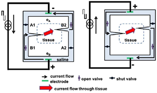
This way the metal electrodes never undergo Faradaic reactions and there are no electrochemical byproducts generated within or external to the device. Conceptually, the SDCS delivers alternating current pulses to electrodes suspended at the opposite ends of a torus filled with ionic solution (termed “saline” in Figure 1).
With each change in stimulation polarity the valves on either side of each electrode change from open-to-closed and closed-to-open, effectively modulating the path for ionic flow through the valves between low impedance and high impedance.
Two extensions connected to the sides of the torus are directed into the body to complete the ionic current circuit. Figure 1 demonstrates this concept, comparing two states of the apparatus. In both panels of the figure, ionic current flows from left to right through the stimulated tissue.
In this way, a continuous AC square wave controlling the apparatus will deliver DC ionic current (iDC) through the tissue from left to right. This system creates a closed-circuit path for the ions to flow, so that the anions that flow into the electrode tube on the right are replaced by the anions that flow out of the electrode tube on the left (Fridman and Della Santina, 2013a).
This concept originated from an attempt to develop a way to maintain endocochlear potential for hearing problems for people suffering from presbycusis, a common age related hearing disorder (Corbett and Clopton, 2004).
This disorder disrupts the important ionic balance between endolymph and perilymph in the cochlea. The idea behind the system proposed by Spelman et al. was to create a mechanism by which electronic current delivered in the form of pulses could be rectified into ionic current flow.
While this original application therapy was not developed further due to the advances in other treatments of age-related hearing loss, such as improved hearing aids and cochlear implants, this work did serve as an inspiration for developing the SDCS.
The SDCS has gone through several conceptual iterations and technological improvements. The original design shown in Figures 1, 2A, suffered from current flow interruptions due to valve transition timing.
During state transitions, the valves would be closed or open simultaneously for a short duration at the same time, causing a short or an open circuit and resulting in interruptions in current flow at the output (Fridman and Della Santina, 2013a). The first solution to the problem of current flow interruption used two SDCS systems that worked in tandem shown in Figure 2B (Fridman and Della Santina, 2013b; Ou and Fridman, 2017).
The system on the left would deliver the current to the tissue, while the system on the right would switch its valve states; the control of the current flow would switch electronically from the system on the left to the one on the right and the right system would change valve states, and then the process would repeat. Even though this solution solved the problem of current flow interruptions, the system suffered from high power requirements due to the need to operate eight independent valves.
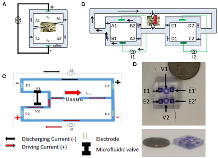
The next design iteration addressed the problem of current flow interruption, and power consumption by reducing the number of valves to just two and requiring only one actuator to control these valves (Fridman, 2017).
The basic construction is diagrammed in Figure 2C. Conceptually, this construction drives the current through the tissue using one current source, while the second discharges. During the valve switch, both valves are open for a short time, while the current sources ensure the proper amount of DC current flow through the tissue.
The microfluidic prototype of this SDCS system is shown in Figure 2D. The valves are designed to be controlled on the PDMS chip using a shape memory alloy Nitinol muscle wire. The valves have been shown to operate for over 1 million cycles (Cheng et al., 2017, 2018; Fridman, 2017).
An alternative direction to mitigate electrical/biological interface concerns has been to develop an organic electronic ion pump (OEIP) that can deliver charged molecules directly from a reservoir to neural tissue via electrophoresis (Moulton et al., 2012; Arbring Sjöström et al., 2018).
OEIP delivery of neurotransmitters has been shown to modulate neural activity both in-vitro- and in-vivo- (Isaksson et al., 2007; Simon et al., 2009, 2010, 2015), which could allow for OIEP-mediated neuromodulation to produce a more naturalistic control of neural activity.
While OIEPs typically use DC current to drive electrophoresis, OIEPs are typically very low voltage and do not influence the membrane voltage of target neurons via a direct electric field effect, but rather by either the electrophoretic modulation of neurotransmitter or extracellular ionic concentrations (Simon et al., 2010; Larsson et al., 2013; Tarabella et al., 2013; Arbring Sjöström et al., 2018).
Given the radically different mechanism of neural interaction that OIEPs employ compared to traditional or even ionic DC electrical stimulation, a full discussion of their mechanisms and potential applications is beyond the scope of this review. However, the reviews cited here discuss the development and function of OIEPs comprehensively (Svennersten et al., 2011; Moulton et al., 2012; Larsson et al., 2013; Arbring Sjöström et al., 2018).
Electrical Stimulation—Neuron Interaction
With improvements to DC stimulation technology that reduce or even eliminate the safety concerns associated with toxic byproducts at the metal electrode-tissue interface, it becomes important to understand how the resulting focal iDC interacts with neurons.
Unless explicitly mentioned, from here-on in the review it should be assumed that we are discussing only the effects of direct ionic current flow through the body and not the effects of undesirable electrochemical reactions at the tissue interface.
Current Flow Through Tissue
The electric field associated with current delivered to an electrode in contact with the body depends on the impedance of the tissue through which this current travels. Even though the impedances differ greatly between different types of body tissues (Geddes and Baker, 1967; Pethig, 1987), each individual type of tissue impedance can be loosely modeled as a parallel resistor/capacitor pair, with the capacitance of the tissue modeling the impedance associated with the cell membranes, and the resistive components modeling the interstitial spaces (Gudivaka et al., 1999; Kyle et al., 2004).
More accurately, finite element models (FEM) often include realistic morphologies of tissue and electric properties that include both conductivity and permittivity (Grant and Lowery, 2010; Joucla and Yvert, 2012; Wongsarnpigoon and Grill, 2012; Joucla et al., 2014). Capacitive and even dispersive impedances (in which permittivity varies as a function of frequency) are important when current propagation through tissue is pulsed at sub-millisecond duration (Grant and Lowery, 2010).
These considerations are simplified for electrical stimuli at low DC-like frequencies, and can be reduced to models of purely resistive current propagation and static electric fields (Plonsey and Heppner, 1967). Just as for pulsatile stimuli, electric field orientations can be modified by introducing multiple electrodes, whose resulting electric fields would add in a standard linear superposition.
Source:
Duke


[…] Next-generation of brain implants include more than a thousand electrodes and… […]